
Wireless data and power transfer over an inductive telemetry link

a technology of inductive telemetry and wireless transmission, applied in the direction of wireless architecture, instruments, high-level techniques, etc., can solve the problems of requiring a high data rate for transmission of recorded data, most devastating medical conditions, and difficult 6 mbps data rate, etc., to achieve high data rate, low power, and efficient transmission power

Active Publication Date: 2018-01-16
RGT UNIV OF CALIFORNIA
View PDF18 Cites 3 Cited by
  • Summary
  • Abstract
  • Description
  • Claims
  • Application Information

AI Technical Summary

Benefits of technology

The invention allows for the efficient transmission of high-speed data while using less power than existing methods. It achieves this by using a new modulation technique called synchronous cyclic on-off keying (COOK) which retains most of the energy in the resonant inductive tank during modulation. This allows for high data rates with low power. The invention also uses a multi-phase phase-locked loop (PLL) to control the timing and power in generating multiple constant voltage supplies and time-varying stimulation voltage signals. This feature allows for precise control of power supply and waveform, saving energy and avoiding heating of biomedical implants and other wireless sensors and actuators.

Problems solved by technology

There are many challenges when creating an implantable device.
Issues such as reliable and fast bidirectional data communication, efficient power delivery to the implantable circuits, low noise and low power for the recording part of the system, and delivery of safe stimulation to avoid tissue and electrode damage are some of the challenges faced by the microelectronics circuit designer.
Injuries or diseases that affect the nervous system can result in some of the most devastating medical conditions.
A key challenge with respect to power and data telemetry for this device, and others, comes from where it needs to be placed—within a very limited space in the body.
Other obstacles include that the rate uplink telemetry requires a high data for transmission of recorded data.
This over 6 Mbps data rate is challenging because of its very limited amount of power, which is transferred wirelessly.
High power transfer efficiency requires high Q, normally restricting the data rate due to the long rectification-off time.
Where only two coils are used (for both power and data), there is a risk of disruption in power delivery if the short is applied for too long to the implant coil.
However, this scheme loses energy whenever shorting the LC tank because of the subsequent reversal of LC resonance and the recovery time after transmitting one bit limits the data rate.
Approaches using higher RF bands require additional complexity in circuits and antenna structures, including sophisticated power management circuitry.

Method used


Image

  • Wireless data and power transfer over an inductive telemetry link
  • Wireless data and power transfer over an inductive telemetry link
  • Wireless data and power transfer over an inductive telemetry link

Examples


Embodiment Construction

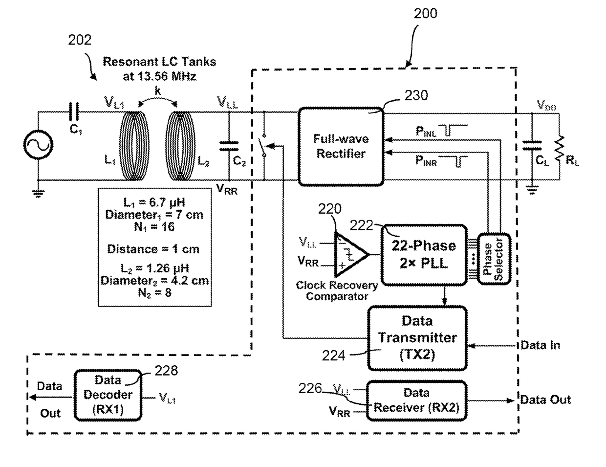
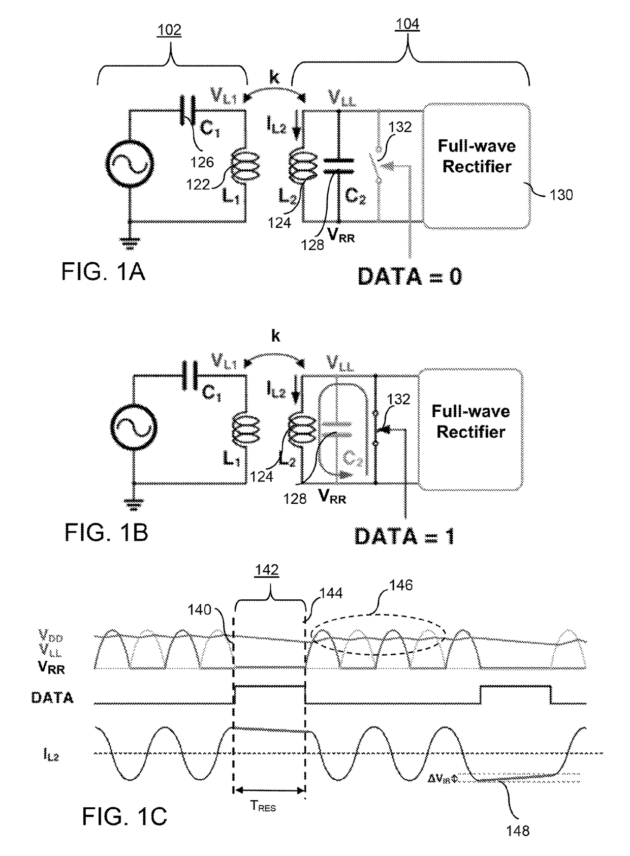
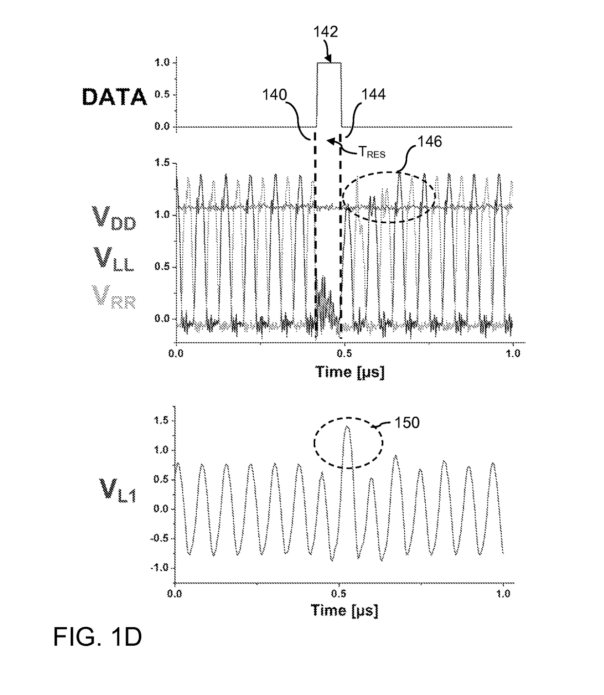
[0023]According to embodiments of the present invention, synchronous cyclic on-off keying (COOK) is exploited to retain almost all stored energy in the LC (inductor-capacitor) resonant tank during modulation of the carrier signal, thus providing the ability to achieve very high data rate with very low power consumption.

[0024]Referring to FIGS. 1A and 1B, the block diagram for the inventive data modulation scheme is same as LSK—the difference lies in the timing when it closes the switch and opens the switch. Briefly, the basic components of the inductive telemetry circuit 100 include an external unit 102 and an internal unit 104, with mutually coupled external coil (L1) 122 and implanted coil (L2) 124. The degree of coupling between these two coils can be described in terms of M=k√{square root over (L1L2)} their mutual inductance. The coupling factor, k, corresponds to the proportion of the external coil's 122 field that is captured by the implanted coil 124. The external capacitor (...


PUM


Abstract

A telemetry device includes a resonant inductive link with a primary LC tank and secondary LC tank configured to resonate at a carrier frequency. A modulator assembly in communication with the secondary LC tank implements data-synchronized cyclic on-off keying modulation (COOK) to periodically create a short across the secondary LC tank in response to a pulse from a phase selector and phase-locked loop. During the full cycle-length of the short, data can be transmitted across the inductive link while the charge across the secondary LC tank is preserved. Power may be transferred across the link during non-shorted cycles.

Description

RELATED APPLICATIONS[0001]This application is a 371 national stage filing of International Application No. PCT / US2015 / 034944, filed Jun. 9, 2015, which claims the benefit of the priority of U.S. Application No. 62 / 009,699, filed Jun. 9, 2014, which is incorporated herein by reference in its entirety.FIELD OF THE INVENTION[0002]The invention relates to a method and apparatus for efficiently transmitting power and data wirelessly over an inductive telemetry link, and more specifically to a modulation scheme for high bit rate, low BER data transfer with low power consumption.BACKGROUND OF THE INVENTION[0003]Implantable medical devices provide therapy to treat numerous health conditions as well as monitoring and diagnosis. Over the years, the development of these devices has seen remarkable progress due to tremendous advances in microelectronics, electrode technology, packaging and signal processing techniques. Many of today's implantable devices use wireless technology to perform the d...

Claims


Application Information

Patent Timeline
Patent Type & Authority Patents(United States)
IPC IPC(8): G08C19/06H04Q9/00H04B5/00G08C19/12
CPCH04Q9/00H04B5/0037H04B5/0075H04Q2209/88H04Q2209/40H04B5/24H04B5/79Y02D30/70
Inventor HA, SOHMYUNGCAUWENBERGHS, GERT
Owner RGT UNIV OF CALIFORNIA
Learn More