Display device
a display device and display technology, applied in the field of display devices, can solve the problems of limited irradiation area per laser light source and irradiation area per unit time, difficult to process a large-sized substrate with an insulating surface in a short time, and achieve the effects of fewer external connection terminals, high image quality, and reduced production costs
- Summary
- Abstract
- Description
- Claims
- Application Information
AI Technical Summary
Benefits of technology
Problems solved by technology
Method used
Image
Examples
embodiment 1
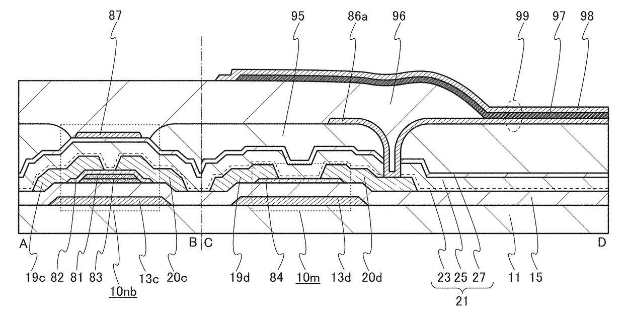
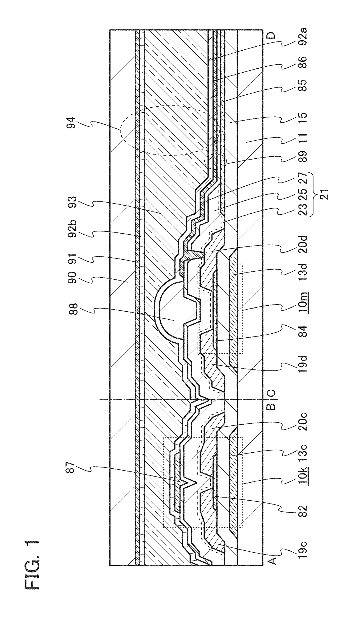
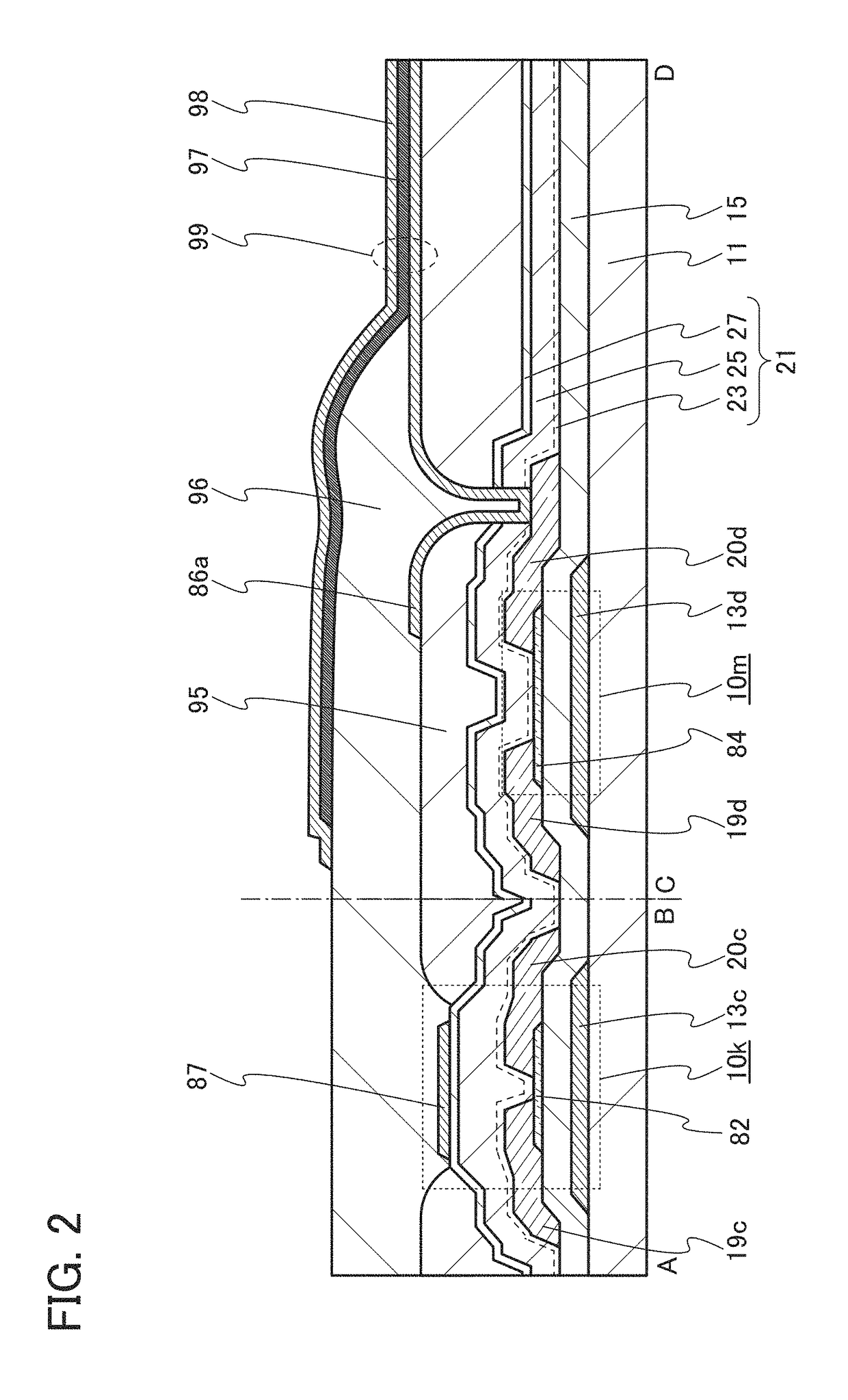
[0096]In this embodiment, a semiconductor device of one embodiment of the present invention and a method for manufacturing the semiconductor device are described with reference to drawings. Here, a liquid crystal display device and a light-emitting device are described as examples of the semiconductor device, with reference to FIG. 1, FIG. 2, FIGS. 3A to 3C, FIGS. 4A and 4B, and FIGS. 5A and 5B. In this embodiment, the semiconductor devices each include a first transistor and a second transistor, which include oxide semiconductor films with different structures.
[0097]First, a liquid crystal display device is described.
[0098]FIG. 1 is a cross-sectional view of the liquid crystal display device; a transistor formed in a driver circuit portion is shown in a cross section A-B, and a transistor formed in a pixel portion is shown in a cross section C-D.
[0099]A transistor 10k shown in the cross section A-B in FIG. 1 includes a gate electrode 13c over a substrate 11, a gate insulating film ...
embodiment 2
[0235]In this embodiment, a structure example of a display device of one embodiment of the present invention is described.
[0236]FIG. 6A is a top view of the display device of one embodiment of the present invention. FIG. 6B is a circuit diagram illustrating a pixel circuit that can be used in the case where a liquid crystal element is used in a pixel in the display device of one embodiment of the present invention. FIG. 6C is a circuit diagram illustrating a pixel circuit that can be used in the case where an organic EL element is used in a pixel in the display device of one embodiment of the present invention.
[0237]The transistor in the pixel portion can be formed in accordance with the above embodiment. Further, the transistor can be easily formed as an n-channel transistor, and thus, part of a driver circuit that can be formed using an n-channel transistor is formed over the same substrate as the transistor in the pixel portion. Thus, the pixel portion and the driver circuit are ...
embodiment 3
[0264]In this embodiment, one embodiment that can be applied to the oxide semiconductor film in any of the transistors included in the semiconductor device described in Embodiment 1 is described.
[0265]The oxide semiconductor film may include one or more of the following: an oxide semiconductor having a single-crystal structure (hereinafter referred to as a single-crystal oxide semiconductor); an oxide semiconductor having a polycrystalline structure (hereinafter referred to as a polycrystalline oxide semiconductor); an oxide semiconductor having a microcrystalline structure (hereinafter referred to as a microcrystalline oxide semiconductor), and an oxide semiconductor having an amorphous structure (hereinafter referred to as an amorphous oxide semiconductor). Further, the oxide semiconductor film may be formed using a CAAC-OS film. Furthermore, the oxide semiconductor film may include an amorphous oxide semiconductor and an oxide semiconductor having a crystal grain. Described below...
PUM
 Abstract
Description
Claims
Application Information
 - R&D
- Intellectual Property
- Life Sciences
- Materials
- Tech Scout
- Unparalleled Data Quality
- Higher Quality Content
- 60% Fewer Hallucinations
Browse by: Latest US Patents, China's latest patents, Technical Efficacy Thesaurus, Application Domain, Technology Topic, Popular Technical Reports.
© 2025 PatSnap. All rights reserved.Legal|Privacy policy|Modern Slavery Act Transparency Statement|Sitemap|About US| Contact US: help@patsnap.com


