Led thyristor switched constant current driver

a constant current driver and led technology, applied in the direction of light sources, electrical appliances, lighting apparatuses, etc., can solve the problems of generating electromagnetic interference (emi), affecting the useful life of led, and unable to compensate for changes in led load current for ac supply voltage and ambient temperature variations with conventional biasing schemes, etc., to achieve the effect of short bill of materials and maximum useful life of led

Active Publication Date: 2017-11-14
PAPANICOLAOU ELIAS S
View PDF6 Cites 35 Cited by
  • Summary
  • Abstract
  • Description
  • Claims
  • Application Information

AI Technical Summary

Benefits of technology

The present invention is a circuit for driving a LED load using a power device, such as a MOSFET, JFET, or transistor. The circuit compensates for changes in power supply voltage and temperature variations to keep the LED load current constant. This is achieved by using a thyristor with temperature compensation to maintain a constant biasing point on the power supply voltage waveform. The circuit is durable, versatile, and cost-effective, with a short bill of materials and minimal manufacturing costs. The technical effects of this invention include increased durability and versatility of LED load driving circuits and cost-effectiveness.

Problems solved by technology

It should also be noted here that thyristor circuits, as is the case with other high frequency switching LED circuits, generate electromagnetic interference (EMI).
Without the thyristor compensation for changes in the LED load current for AC supply voltage and ambient temperature variations could not have been achieved with conventional biasing schemes.
However, any shift in the triggering point on the AC supply voltage waveform would be minor and would not affect the proper operation with AC supply voltage variations.

Method used


Image

  • Led thyristor switched constant current driver
  • Led thyristor switched constant current driver
  • Led thyristor switched constant current driver

Examples


Embodiment Construction

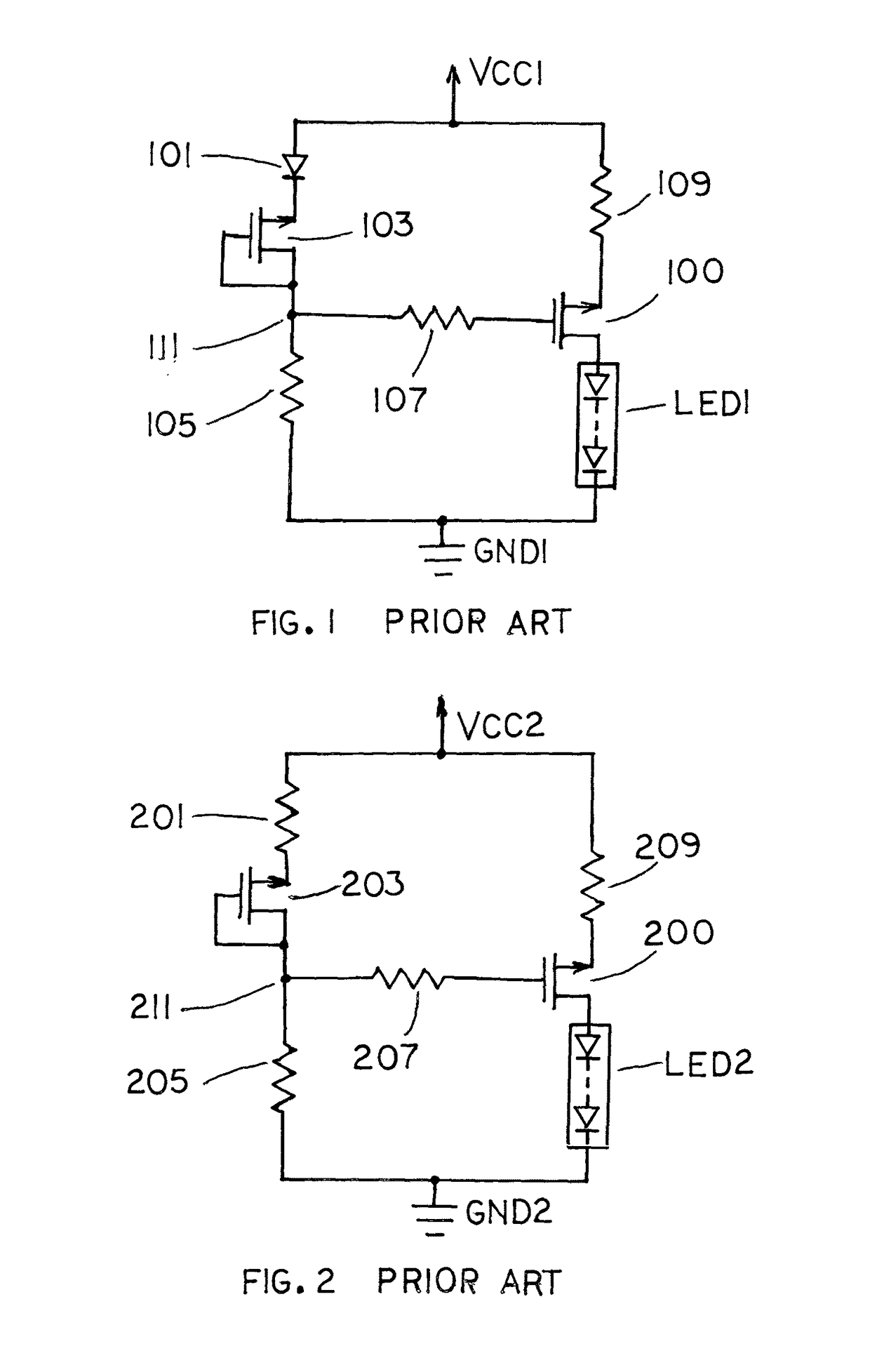
[0027]Shown in FIG. 1 is a prior art current source driver for LED and other loads. The load current in this circuit is independent of supply voltage changes but not for ambient temperature variations. In the circuit both transistors are the P-CHANNEL MOSFET type with source, gate and drain terminals as depicted. These transistors can also be substituted with the PNP type of transistors with emitter, base and collector terminals being the MOSFET source, gate and drain terminals respectively. AC supply Vcc1 is the positive side of a DC voltage source or the positive side of an unsmoothed rectified AC voltage source. The negative side of voltage source Vcc1 is connected to ground GND1. The source terminal of transistor 100 is connected to supply Vcc1 by way of resistor 109. The drain terminal of transistor 100 is returned to ground GND1 via load LED1. Resistor 107 is connecting the gate terminal of transistor 100 to node 111 on the bias string comprising diode 101, diode connected tra...


PUM


Abstract

A circuit for controlling power to a load from a rectified AC supply is disclosed. The load like an LED or another type is driven by a power device such as a MOSFET or a transistor. The power device is biased from a resistive string which also includes a thyristor switch in series combination. At a specific trigger or conduction angle of the thyristor switch the proper bias for the power device is obtained to enable the load current to remains fairly constant with AC supply voltage fluctuations or loading. Furthermore the trigger circuit of the thyristor switch is properly configured in order for the load current to stay constant or even change with ambient temperature variations as well.

Description

FIELD OF THE INVENTION[0001]The present invention relates to a thyristor switched current source circuit with compensation for power supply voltage and ambient temperature variations. It can be used to provide constant current to LED and other loads.WORD AND SYMBOL EXPLANATIONS[0002]Whenever the following words or symbols are encountered in this document their true meaning would be as stated below.[0003]LED: Light emitting diode.[0004]Load: Electrical load[0005]LED load: One LED or more LEDs in series or parallel connections that would allow the LEDs when activated to be forward biased.[0006]deg. C.: Degree or degrees Celsius.[0007]mA: Milliampere or milliamperes. The milliampere is a unit of current equal to one thousandth of an ampere.[0008]mV: Millivolt or millivolts. The millivolt is a unit of voltage equal to one thousandth of a volt.[0009]kohm: Kiloohm or kiloohms. The kiloohm is a unit of electrical resistance equal to one thousand ohms.BACKGROUND OF THE INVENTION[0010]In an ...

Claims


Application Information

Patent Timeline
IPC IPC(8): H05B33/08H05B44/00
CPCH05B33/0815H05B33/0809H05B45/382
Inventor PAPANICOLAOU, ELIAS S
Owner PAPANICOLAOU ELIAS S
Why Eureka
Try Eureka