
Standby electrical energy storage devices

a technology of electrical energy storage and standby, which is applied in the direction of cell components, cell component details, batteries, etc., can solve the problems of long-term chemical degradation, finite charge/discharge lifetime of rechargeable cells, etc., to reduce manoeuvrability and speed of vehicles, increase the payload capability of satellites substantially, and save weight and bulk

Inactive Publication Date: 2017-11-14
BAE SYSTEMS PLC
View PDF12 Cites 0 Cited by
  • Summary
  • Abstract
  • Description
  • Claims
  • Application Information

AI Technical Summary

Benefits of technology

The invention is a new type of battery that solves the problem of heavy weight and limited maneuverability in vehicles. By using a separator structure that prevents short circuits while allowing ions to pass through, the battery has a void that creates a void within the device. This void can be a cavity, pore, or a void created by a partially bonded separator layer. The distributed nature of the battery also allows for easier design of an aircraft and reduces the need for additional weight. The batteries can be positioned closer to equipment, such as cabin lights and emergency exit systems, as they are part of the aircraft structure and do not need separate accommodation. The invention solves the problem of heavy weight and limited maneuverability in vehicles while providing a reliable and distributed battery solution.

Problems solved by technology

Rechargeable cells also have finite charge / discharge lifetimes and can suffer from long term chemical degradation even when not used.
This can present reliability issues and so they are not suitable for applications where the power supply must be guaranteed to be available on demand and / or at very short notice.

Method used


Image

  • Standby electrical energy storage devices
  • Standby electrical energy storage devices

Examples


Embodiment Construction

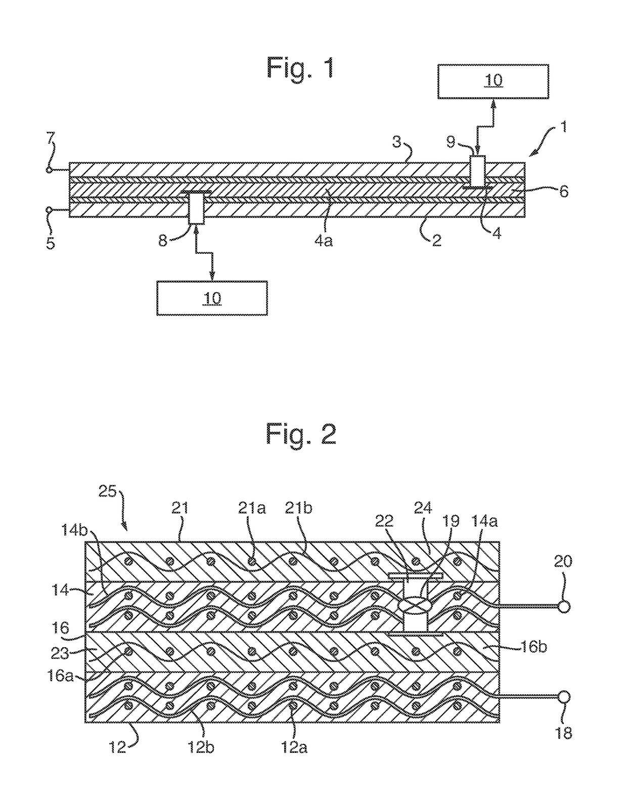
[0041]FIG. 1 shows an example of an electrical energy storage device 1, comprising a first electrode structure 2 which is spaced apart from a second electrode structure 3 by a separator structure 6. The electrodes structures 2, 3 may be connected to suitable electrode contacts 5, 7 respectively to permit electrical charging and discharging of the device.

[0042]The electrodes 2, 3 have valves 8, 9 respectively, to allow an electrolyte 4 to be charged from the reservoir 10, into the void 4a within the separator layer 6, in this arrangement a partially bonded separator layer.

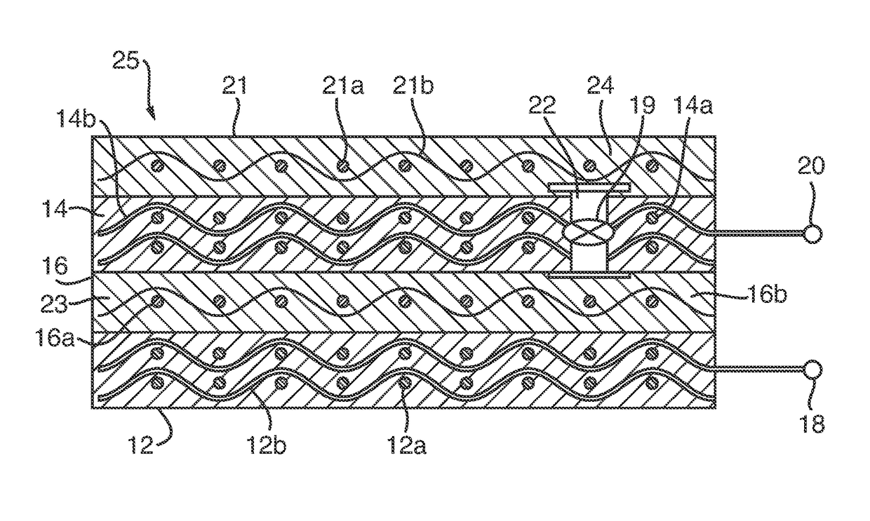
[0043]FIG. 2 shows an example of a component integral with an alkaline standby battery, depicted generally at 25, comprising an anode structure 12 which is spaced apart from a cathode structure 14 by a separator structure 16, comprising at least one void 23 (ie a cavity) which is to be filled with the electrolyte 24 stored in reservoir layer 21 . A chamber 22 with a valve 19 is located between the separator structur...


PUM

PropertyMeasurementUnit
particle sizesaaaaaaaaaa
electrically conductiveaaaaaaaaaa
electrically insulatingaaaaaaaaaa

Abstract

This invention relates to the formation of standby structural composite electrical energy storage devices, and a method of producing same. The device may be a standby battery or supercapacitor with first and second electrodes which are separated by a separator structure, wherein the device contains an electrolyte retained in a reservoir. The use of at least one valve allows the addition, removal of electrolyte fluids, and venting of any outgassing by products.

Description

RELATED APPLICATIONS[0001]This application is a national phase application filed under 35 USC §371 of PCT Application No. PCT / GB2014 / 050571 with an International filing date of Feb. 26, 2014 which claims priority of GB Patent Application 1303766.8 filed Mar. 4, 2013 and EP Patent Application 13275046.4 filed Mar. 4, 2013. Each of these applications is herein incorporated by reference in its entirety for all purposes.FIELD OF THE INVENTION[0002]The invention relates to the formation of standby structural composite electrical energy storage devices.BACKGROUND OF THE INVENTION[0003]Rechargeable cells suffer from self-discharge so must be topped up by periodic charging. Rechargeable cells also have finite charge / discharge lifetimes and can suffer from long term chemical degradation even when not used. This can present reliability issues and so they are not suitable for applications where the power supply must be guaranteed to be available on demand and / or at very short notice.[0004]Prim...

Claims


Application Information

Patent Timeline
Patent Type & Authority Patents(United States)
IPC IPC(8): H01M6/32H01G11/18H01G11/56H01G11/62H01G11/78H01M4/36H01G11/04H01M2/16H01M2/18H01M4/12H01M4/24H01M4/34H01M50/437
CPCH01M6/32H01G11/18H01G11/56H01G11/62H01G11/78H01M2/1613H01M2/1666H01M2/18H01M4/12H01M4/244H01M4/34H01M4/364H01G11/04Y02E60/13H01M2220/20Y02E60/10H01M50/44H01M50/437
Inventor HUCKER, MARTYN JOHNHAQ, SAJADDUNLEAVY, MICHAEL
Owner BAE SYSTEMS PLC
Learn More