
Drive control method and control device which operates according to the method

a technology of drive control and control device, which is applied in the direction of electric motor control, electrical equipment, control systems, etc., can solve the problems of large mechanical oscillation, undesirable restrictions in process design, and vertical mills, and achieve the reduction or increase of drive-side target torque, reduce dynamic load peaks, and reduce the stress on the drivetrain mechanical system.

Active Publication Date: 2017-10-17
SIEMENS AG
View PDF8 Cites 3 Cited by
  • Summary
  • Abstract
  • Description
  • Claims
  • Application Information

AI Technical Summary

Benefits of technology

The invention relates to a method for reducing dynamic load peaks in a drivetrain caused by grinding processes. By adjusting the target torque in the same direction as the torque resulting from the grinding process, the method avoids or reduces the need for excessive dimensioning of the components of the drivetrain. This allows for a more economical and lighter design of the drivetrain. Additionally, the method reduces the need for a coupling between the electric motor and the gearbox, which can also be eliminated. The detection of the actual torque in the drivetrain and the recording of its changes over time can be done using sensors and the associated processing of the sensor data. The invention also allows for the adjustment of the target torque to avoid or reduce the counter torque that can result from the grinding process, reducing stress on the drivetrain and allowing for a lighter design.

Problems solved by technology

Vertical mills of the type mentioned above with a grinding plate rotating about the vertical and grinding rollers above the grinding plate tend to be subject to significant mechanical oscillation, as in simple terms a vertical mill is an oscillatory system in the form of a damped two-mass oscillator.
However this results in undesirable restrictions in process design which have a negative impact in many areas.
The interaction of these stress influences results in a complex load cycle, which can even instigate resonant oscillation.
In addition to drivetrain oscillation a non-stable grinding bed, in other words a fluidizing grinding bed or one characterized by waviness, can also result in extreme oscillation states of the mill, in particular mill rumble.
Finally the grinding of natural products makes it largely unpredictable how the grinding process should be set to insure quiet running of the mill.
It is therefore always a challenge for the operator in control to set the correct process parameters.
Ultimately the drive alone can alleviate an unfavorably set process but it cannot correct it.
However a coupling is known to be an expensive part that is subject to wear and the way in which oscillations are damped by means of a coupling is based on the conversion of oscillation energy to heat, which has a negative impact on the energy balance sheet of the vertical mill.

Method used


Image

  • Drive control method and control device which operates according to the method
  • Drive control method and control device which operates according to the method
  • Drive control method and control device which operates according to the method

Examples


Embodiment Construction

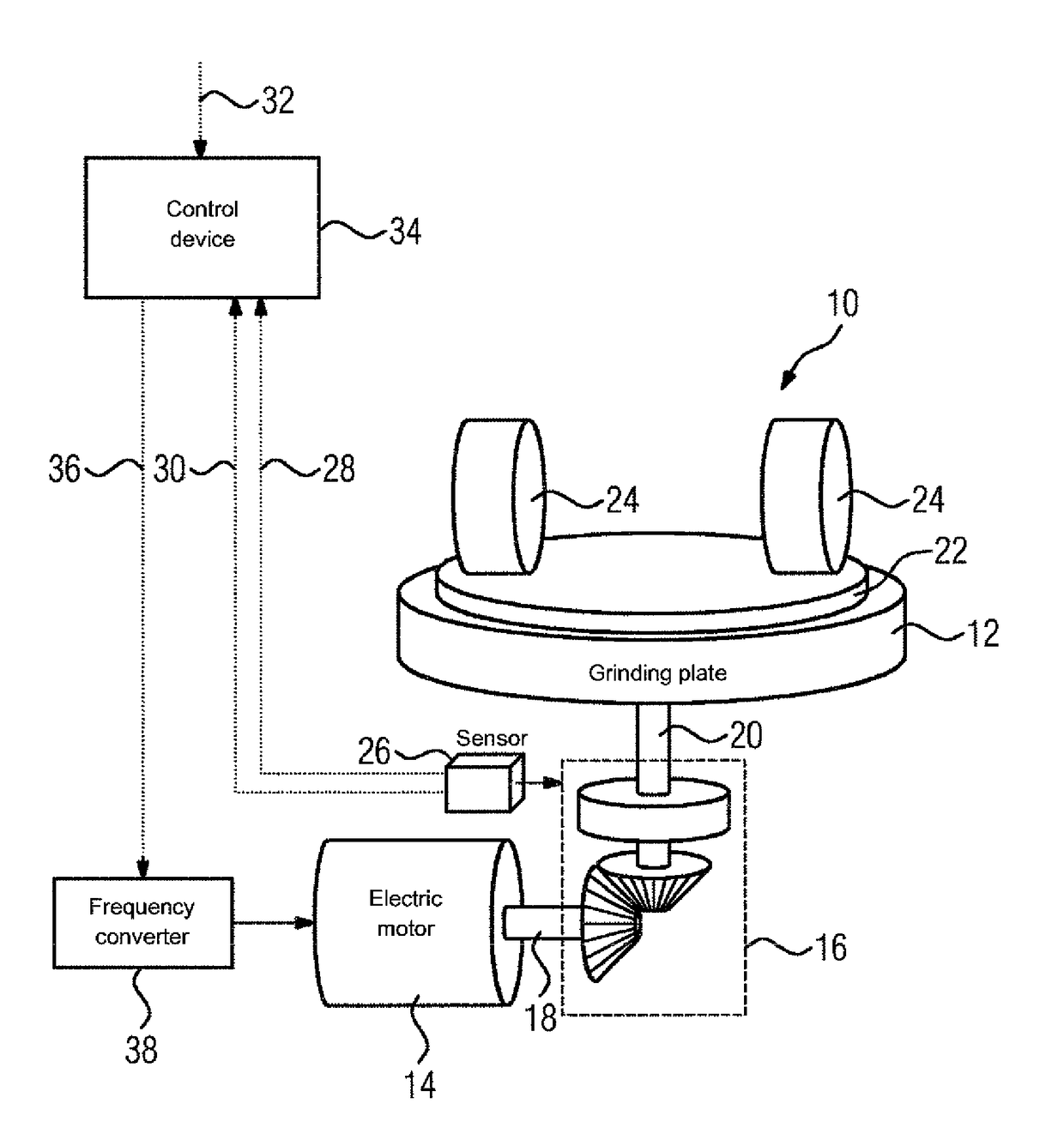
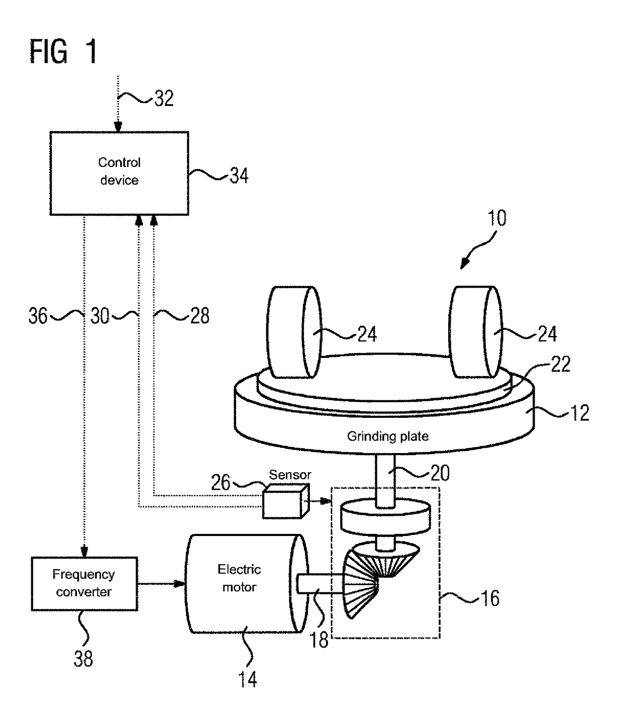
[0037]FIG. 1 shows a highly simplified schematic diagram of a vertical mill 10 for crushing brittle materials, for example cement raw materials. The vertical mill 10 comprises a grinding plate 12 which can be rotated about the vertical. The grinding plate 12 is driven by means of a heavy duty drive in the form of at least one motor, in particular at least one electric motor 14, and in the example illustrated here by means of a gearbox 16 present between the or each electric motor 14 and the grinding plate 12. The gearbox 16 here is shown as a bevel gearing with an adjoining planetary gearbox (not shown in detail) without renouncing greater generality. The gearbox 16 can also comprise for example a helical gearing or the like and / or an upstream or adjoining planetary gearbox or the like.

[0038]The vertical mill 10 comprises at least one driven shaft. In the diagram in FIG. 1 the vertical mill 10 comprises a motor shaft 18 as the drive-side shaft and a grinding plate shaft 20 as the ta...


PUM


Abstract

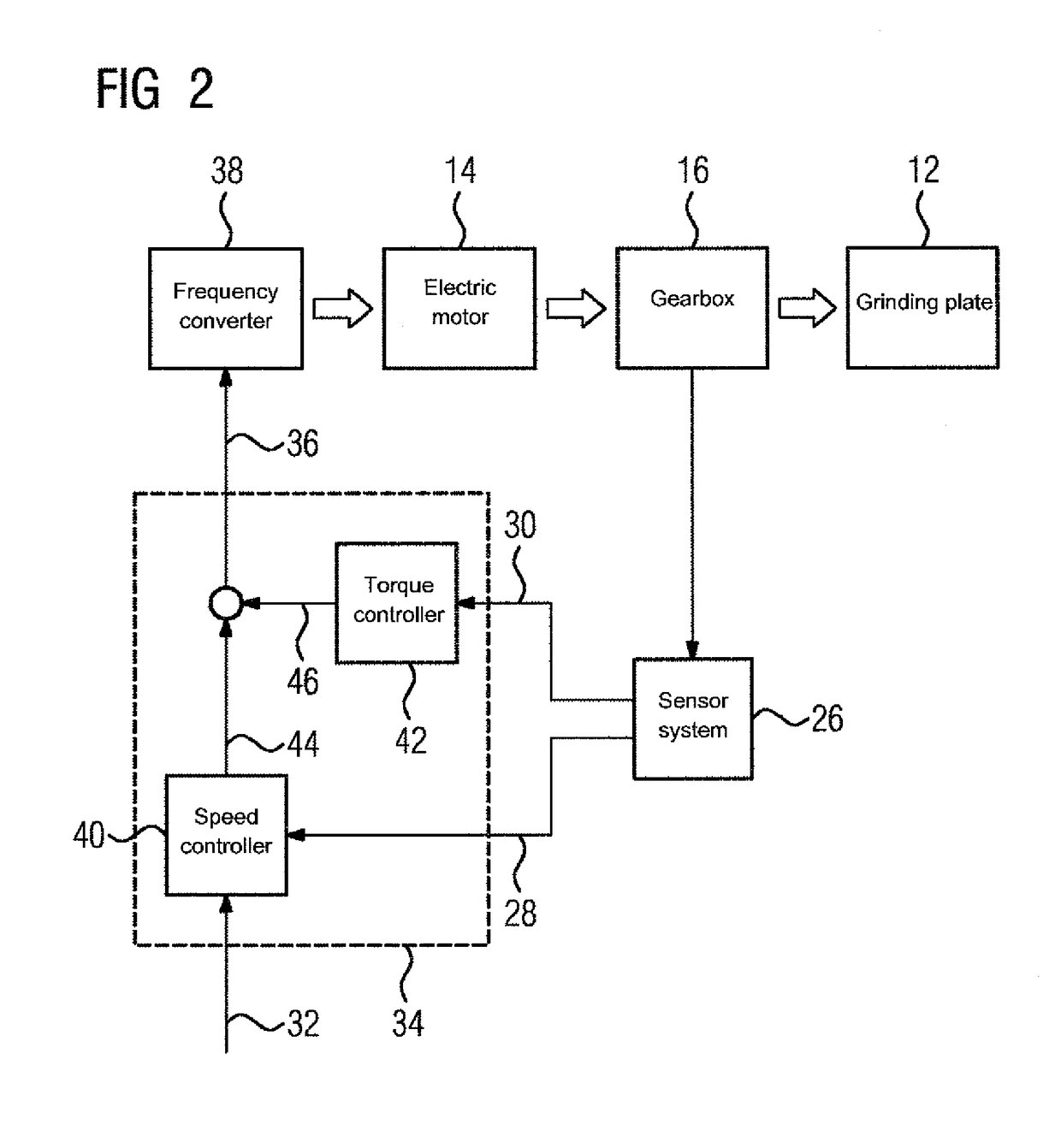
A method and a device for controlling the drive of a vertical mill having a grinding plate rotatable about the vertical axis are disclosed. The grinding plate can be driven by an electric motor and a drivetrain with a gearbox. An actual rotational speed and a drivetrain torque with respect to the drivetrain are detected and are fed to a control device together with a specified target rotational speed. The control device generates an output signal for a target torque based on the actual rotational speed and the target rotational speed and based on the drivetrain torque such that the resulting target torque is reduced or increased in the same direction as a torque resulting from the milling process.

Description

CROSS-REFERENCES TO RELATED APPLICATIONS[0001]This application is the U.S. National Stage of International Application No. PCT / EP2013 / 068261, filed Sep. 4, 2013, which designated the United States and has been published as International Publication No. WO 2014 / 111177 and which claims the priority of German Patent Application, Serial No. 10 2013 200 578.4, filed Jan. 16, 2013, pursuant to 35 U.S.C. 119(a)-(d).BACKGROUND OF THE INVENTION[0002]The present invention relates to a drive control method, specifically a drive control method for a heavy duty drive, in particular a heavy duty drive of a vertical mill designed to crush brittle materials, for example cement raw materials, as well as a control device for implementing the method and a corresponding drive system for a vertical mill that operates according to the method.[0003]Vertical mills of the type mentioned above with a grinding plate rotating about the vertical and grinding rollers above the grinding plate tend to be subject t...

Claims


Application Information

Patent Timeline
Patent Type & Authority Patents(United States)
IPC IPC(8): B02C25/00B02C15/00H02P31/00
CPCB02C25/00B02C15/007H02P31/00B02C15/02B02C2015/008B02C15/06
Inventor KLOTZEK, ANDREASKUBE, ANDREASPOTTER, FRIEDHELM
Owner SIEMENS AG
Learn More