
Method for interference-robust transmitter placement in wireless mesh networks

a transmitter and wireless mesh technology, applied in the field of communication systems, can solve the problems of low equipment and little technological prowess, difficult to defend against, and particularly vulnerable to attack and exploitation of wmn

Active Publication Date: 2017-10-10
THE UNITED STATES OF AMERICA AS REPRESENTED BY THE SECRETARY OF THE NAVY
View PDF2 Cites 3 Cited by
  • Summary
  • Abstract
  • Description
  • Claims
  • Application Information

AI Technical Summary

Benefits of technology

The patent describes a computer system that designs a wireless network that can resist interference from jammers or other sources of electromagnetic interference. The system takes into account the specific placement of jammers and their impact on coverage. The system selects optimal locations for access points based on minimizing the impact of the most disruptive jammers. The system can also display a visual representation of the area and the resulting coverage. Overall, the system ensures that the wireless network is resilient to jamming and other interference.

Problems solved by technology

The wireless access medium of a WMN makes it particularly vulnerable to attack and exploitation.
Powerful commercial and military jamming systems are readily available, but this type of attack can be conducted with inexpensive equipment and little technological prowess, and can be very challenging to defend against.
Even unintentional interference can be as harmful as an intentional attack.
However, they also fail to consider jammers that could then move and attack the newly-configured network.
Others have similarly considered the deliberate placement of jammers by an intelligent adversary (called the attacker) to maximally disrupt network operation, but have not investigated a continuous space for jammer placement (and therefore an infinite number of possible locations).

Method used


Image

  • Method for interference-robust transmitter placement in wireless mesh networks
  • Method for interference-robust transmitter placement in wireless mesh networks
  • Method for interference-robust transmitter placement in wireless mesh networks

Examples


Embodiment Construction

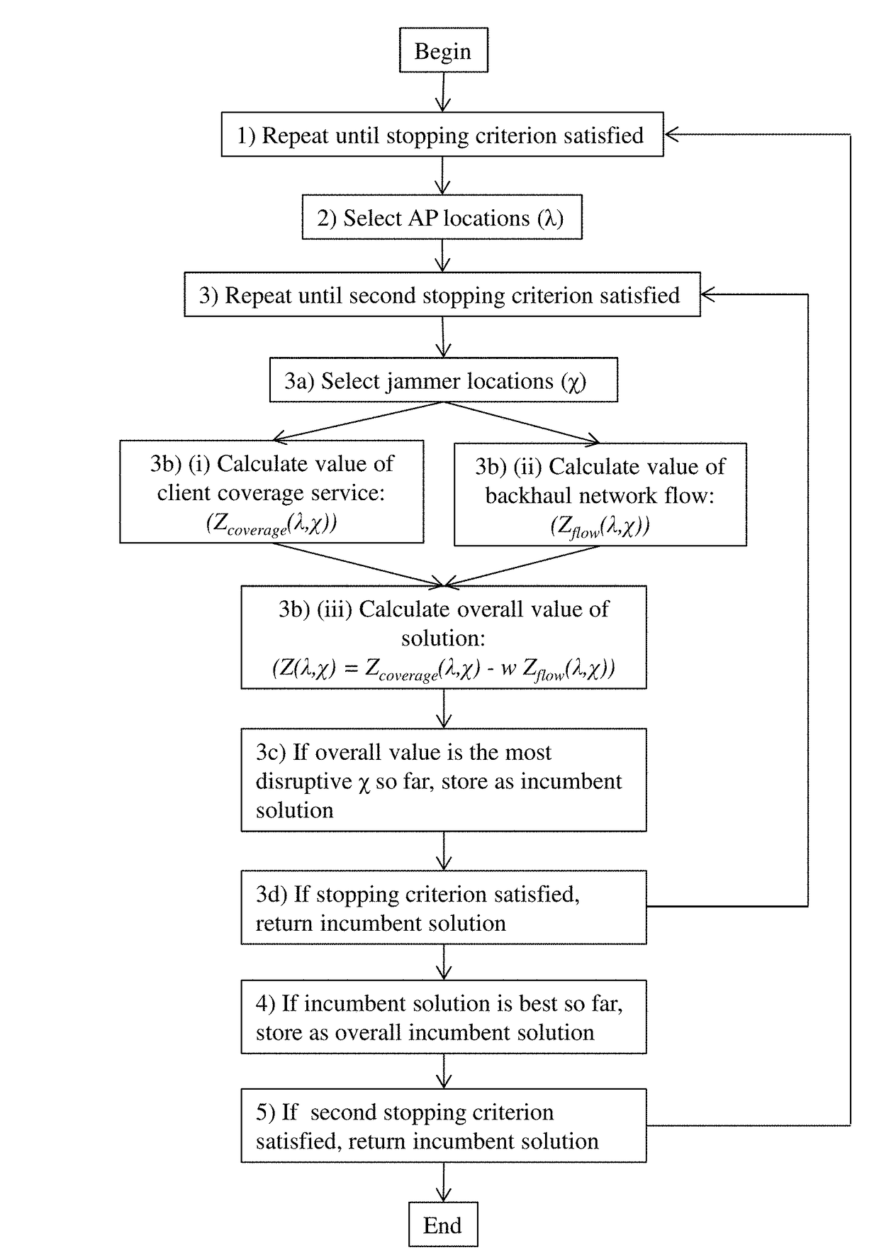
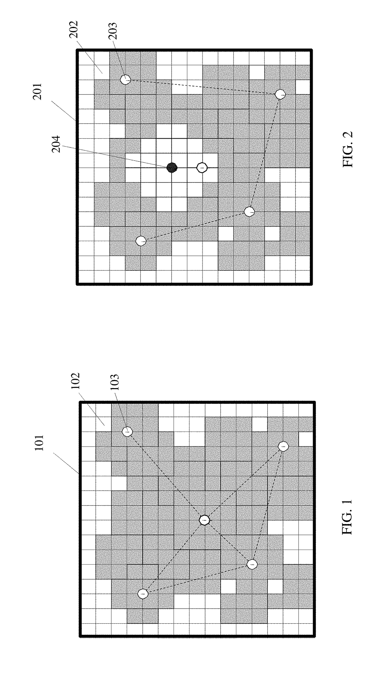
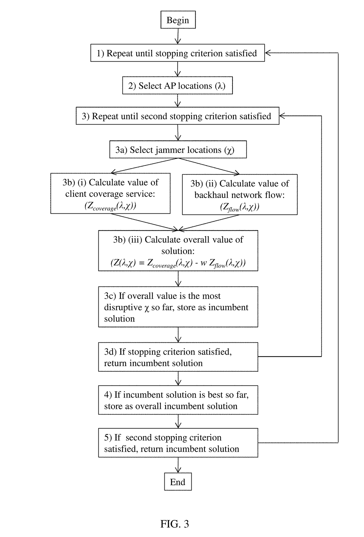
[0029]The disclosure provides a computer-implemented system for establishing a wireless mesh network (WMN) resistant to degradation induced by deliberate jamming or other electromagnetic interference (EMI) emanating from point sources within an operating area. The computer-implemented system may generally be employed against any form of WMN interference in which network performance is a function of the distance between interference sources and WMN Access Points (APs), and provides AP locations that minimize the disruption to client coverage caused by jammers, subject to constraints on network service and considering the effects of radio propagation over terrain. The computer-implemented system utilizes a process which considers network design in the presence of a simulated intelligent adversary capable of observing the WMN and placing jammers to maximally disrupt coverage.

[0030]The computer implemented system comprises a computer-based apparatus which provides AP locations based on ...


PUM


Abstract

The disclosure provides a computer-implemented system for establishing a wireless mesh network resistant to degradation induced by deliberate jamming or other electromagnetic interference emanating from point sources within an operating area. The computer-implemented system provides WMN AP locations that minimize disruptions to client coverage caused by jammers, subject to constraints on network service. The computer-implemented system considers jammers placed by an intelligent adversary and identifies the AP locations λ through quantification of an objective function of the general form Z(λ,χ)=Zcoverage(λ,χ)−w Zflow(λ,χ), where Zcoverage(λ,χ) reflects resulting coverage shortfall, Zflow(λ,χ) reflects traffic flow within the WMN, and w is a scalar reflecting the relative weight of the two terms. The final set of AP locations λ identifies the locations of APs to create a WMN that is the most robust to the worst possible jamming attack. Such an attack could represent the actions of a rational human opponent, or the worst-case positioning of unintentional interference sources such as civilian radios, other RF devices, or high-voltage electrical devices.

Description

CROSS-REFERENCE TO RELATED PATENT APPLICATIONS[0001]This application is a non-provisional application of and claims priority to U.S. Patent Application 62 / 097,938, filed on Dec. 30, 2014, which is hereby incorporated by reference in its entirety.BACKGROUND1. Field of the Invention[0002]The present invention relates generally to communications systems and particularly to wireless mesh networks. Still more particularly, the invention relates to a computer-implemented system for quickly and particularly designing a wireless mesh network to maximize robustness against jamming attacks by an intelligent adversary.2. Description of the Related Art[0003]Wireless mesh networks (WMNs) are interconnected systems of wireless access points (APs) that provide untethered network connectivity for a group of users that require data, voice, and / or video communication. Each AP has two radio devices: the first connects to local client devices, such as laptops and portable digital assistants (PDAs); the...

Claims


Application Information

Patent Timeline
IPC IPC(8): H04W16/18H04W64/00H04K3/00H04W84/18
CPCH04W16/18H04K3/20H04W64/003H04W84/18H04K3/94H04K2203/18H04K2203/34
Inventor NICHOLAS, PAUL J.ALDERSON, DAVID L.
Owner THE UNITED STATES OF AMERICA AS REPRESENTED BY THE SECRETARY OF THE NAVY
Learn More