
Down-hole gas and solids separator utilized in production hydrocarbons

a technology of hydrocarbon production and separator, which is applied in the direction of fluid removal, borehole/well accessories, earthwork drilling and mining, etc., can solve the problems of increasing fracture sand, tubing or artificial lifting mechanism, and a multitude of producing problems for oil and gas operators

Active Publication Date: 2017-09-26
HARBISON FISCHER
View PDF21 Cites 12 Cited by
  • Summary
  • Abstract
  • Description
  • Claims
  • Application Information

AI Technical Summary

Benefits of technology

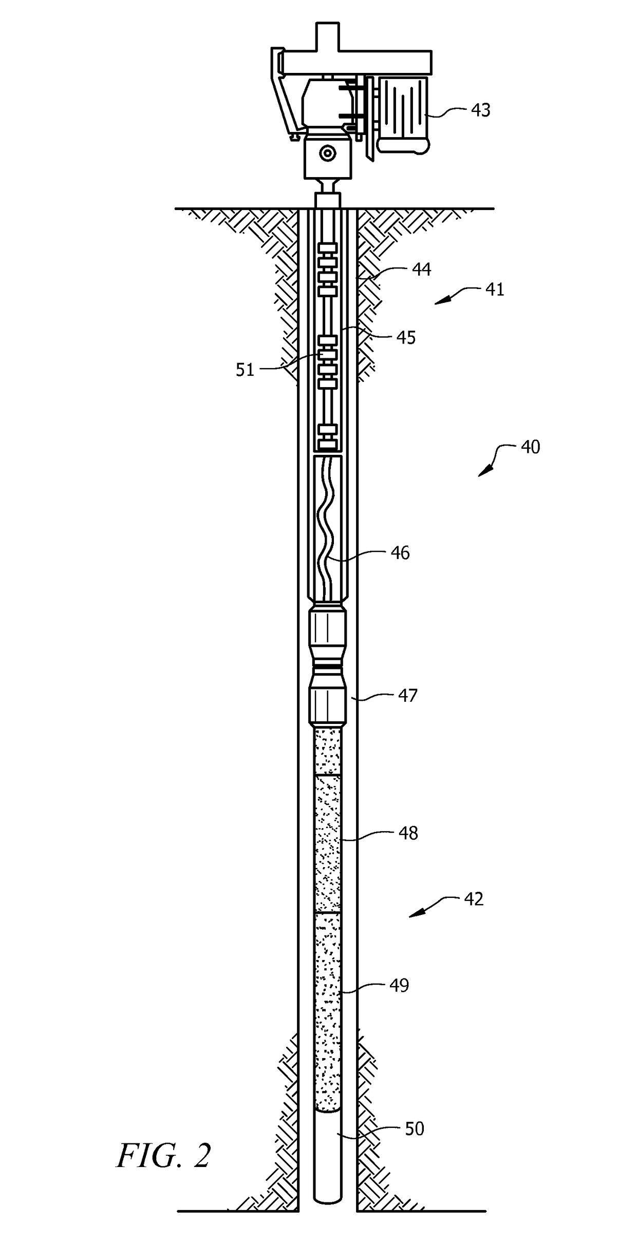
[0006]One embodiment of the invention is a particulate separator for use with a petroleum production well producing a fluid mixture including particulate matter. The separator comprising: a first stage having an outer casing and a first inner tube, the outer casing including intake slots allowing the fluid mixture to enter the space between the outer casing and the first inner tube and to flow downward toward a pump intake, the first stage including at least one baffle in the space between the outer casing and the first inner tube, the at least one baffle assisting in separating gas from the fluid mixture. It further comprises a second stage connected to the first stage and having an outer casing and a second inner tube, the second inner tube having a diameter greater than the first inner tube to cause the velocity of the fluid to increase as it flows downward toward the pump intake, wherein the fluid mixture reaches a downward velocity sufficient to allow the particulate matter in the fluid mixture to continue downward as the fluid is drawn into the inner tube through the pump intake.
[0007]Another embodiment of the invention is a particulate separator for use with a petroleum production well producing a fluid mixture including particulate matter. This embodiment comprises a stage having an outer casing and an inner tube, the outer casing including intake slots allowing the fluid mixture to enter the space between the outer casing and the inner tube and to flow downward toward a pump intake, the stage including at least one baffle in the space between the outer casing and the inner tube, the at least one baffle assisting in separating gas from the fluid mixture.
[0009]Another embodiment of the invention is a method for separating particulates from a fluid mixture in a petroleum production well. The method comprises allowing the fluid mixture to enter an outer casing, the outer casing containing an inner tube; allowing the fluid mixture to fall downward between the outer casing and the inner tube toward a pump intake; providing at least one baffle between the outer casing and the inner tube to assist in separating gas from the fluid mixture; and widening the diameter of the inner tube, increasing the velocity of the fluid mixture sufficiently to allow particulate matter to continue downward as the fluid is drawn into the inner tube through the pump intake.

Problems solved by technology

As hydrocarbons and water flow through the formation, these particulates are carried in the flow stream and can be carried into the production tubing which can cause problems with the tubing or artificial lifting mechanism, such as a rod pump.
With an increase in fracturing of wells designed to increase the well's production, there has been an increase in fracture sand, the most common man-made particulate found at the wellhead.
Natural or man-made particulates can cause a multitude of producing problems for oil and gas operators.
For example, in flowing wells abrasive particulates can “wash through” metals in piping creating leaks and potentially hazardous conditions.
In reservoirs whereby some type of artificial lift is required such as rod pumping, electric submersible pumps, progressive cavity, and other methods, production of particulates can reduce the life of the down-hole assembly and increase maintenance cost.

Method used


Image

  • Down-hole gas and solids separator utilized in production hydrocarbons
  • Down-hole gas and solids separator utilized in production hydrocarbons
  • Down-hole gas and solids separator utilized in production hydrocarbons

Examples


Embodiment Construction

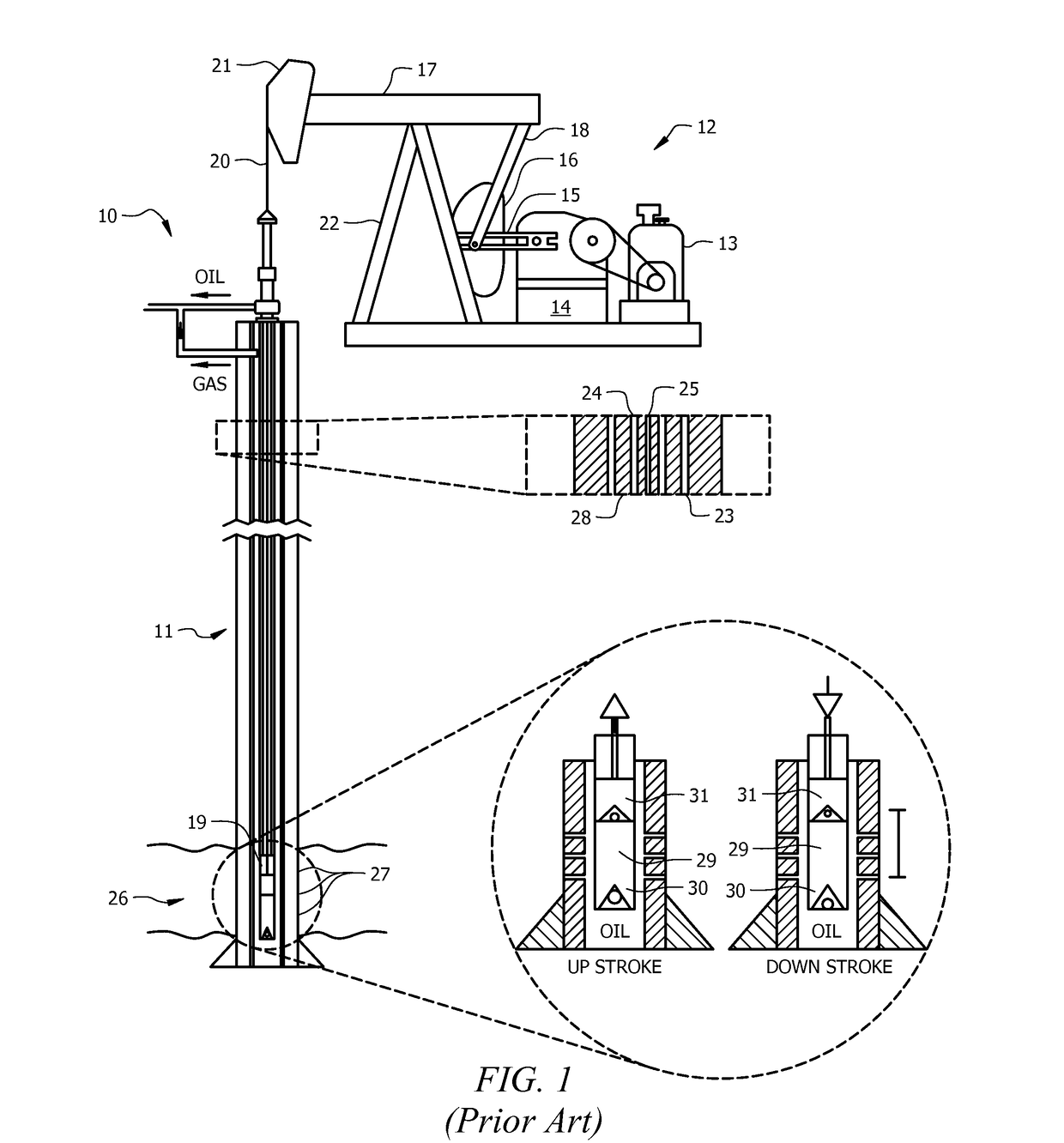
[0020]Referring now to FIG. 1, a diagram of a typical sucker rod pump used in oil wells is described. The sucker rod pump is described only for the purposes of illustrating the operation of a typical oil well and is not intended to be limiting in any manner as the present invention is applicable to any producing oil well including those using any means of artificial lift, such as rod pumping, electric submersible pumps, progressive cavity, and other methods.

[0021]Well 10 includes well bore 11 and pump assembly 12. Pump assembly 12 is formed by a motor 13 that supplies power to a gear box 14. Gear box 14 is operable to reduce the angular velocity produced by motor 13 and to increase the torque relative to the input of motor 13. The input of motor 13 is used to turn crank 15 and lift counter weight 16. As crank 15 is connected to walking beam 17 via pitman arm 18, walking beam 17 pivots and submerges plunger 19 in well bore 11 using bridle 20 connected to walking beam 18 by horse head...


PUM


Abstract

A particulate separator system and method for petroleum wells are described. An embodiment comprises a two stage separator. A fluid mixture flows into an outer casing that surrounds an inner tube. The first stage comprises a number of baffles that help to separate gas from fluid as the fluid mixture falls downward within the casing. A second stage comprises a widened inner tube and a fin causing the fluid mixture to fall radially around the inner tube and downward. As the mixture gains speed the particulate matter is forced to the periphery of the mixture by centrifugal force. A pump intake on the bottom of the inner tube pulls in the fluid while the particulate matter falls away.

Description

CROSS REFERENCE TO RELATED INFORMATION[0001]This application claims the benefit of U.S. Provisional Patent Application No. 61 / 932,483, filed Jan. 28, 2014, titled “Down-hole gas and solids separator utilized in production hydrocarbons.”TECHNICAL FIELD[0002]The present disclosure is directed to petroleum wells and more particularly to gas and liquid separators for wells.BACKGROUND OF THE INVENTION[0003]Petroleum wells can be naturally flowing, injecting or can be produced by any means of artificial lift. Particulates within the production stream, which can include both liquid and gaseous products, can be both naturally occurring and man-made. Such particulates can include sand, silt, and other solids and are a natural byproduct of the producing wells. As hydrocarbons and water flow through the formation, these particulates are carried in the flow stream and can be carried into the production tubing which can cause problems with the tubing or artificial lifting mechanism, such as a ro...

Claims


Application Information

Patent Timeline
Patent Type & Authority Patents(United States)
IPC IPC(8): E21B43/38
CPCE21B43/38E21B43/35
Inventor RAGLIN, JOHN M.
Owner HARBISON FISCHER
Learn More