Ventilated rotor mounting boom for personal aircraft

Active Publication Date: 2017-09-19
WISK AERO LLC
View PDF7 Cites 31 Cited by
  • Summary
  • Abstract
  • Description
  • Claims
  • Application Information

AI Technical Summary

Benefits of technology

The patent describes a personal aircraft with a rotor mounting boom that is safe and efficient, as well as easy to maintain. The boom includes a forward and aft rotor assembly for vertical takeoff and landing and transition to forward flight. The boom is attachable to the wings of the aircraft using fasteners for easy replacement or repair. The orientation of the rotors allows for lateral and fore / aft control of the aircraft without changing its course of flight. Multiple vertical rotors ensure redundancy and thrust in case of failure. The controller assembly on the rotor mounting boom is cooled by airflow caused by the rotor's downwash, which improves controller operation. The controller enclosure includes an air inlet, a heat exchanger, and a raised portion to increase airflow. Overall, the invention provides a compact, safe, and efficient personal aircraft with improved handling and control.

Problems solved by technology

For the rotors to perform this dual function across a range of airspeeds, the rotors are typically quite complex.
Additionally, they utilize mechanically complex systems to control both the collective and cyclic blade angles.
Such rotors are mechanically complex and require maintenance.
The rotors generally rotate at a low speed; this results in heavy transmissions between the rotor and motor.
Because of the mechanical complexity across the entire vehicle system, many parts are single points of failure.
However, many vital components, such as motor controllers, are not duplicated, and are thus still single points of failure.
These components are not duplicated due to design complexity, weight issues, and maintenance concerns.
For example, a motor controller typically needs to be cooled, and including multiple conventional cooling systems on an aircraft increases design complexity and aircraft weight.
Additionally, including multiple conventional cooling systems increases the chances that an aircraft will be taken out of service for maintenance.
Due to the multiple number and independence of the vertical lift rotors, the vertical thrust is redundant and thrust and control remain available even with the failure of any single rotor.

Method used


Image

  • Ventilated rotor mounting boom for personal aircraft
  • Ventilated rotor mounting boom for personal aircraft
  • Ventilated rotor mounting boom for personal aircraft

Examples


second embodiment

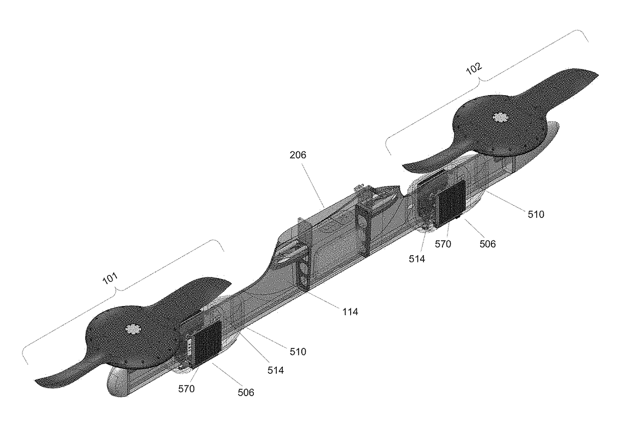
[0044]FIG. 6 illustrates a side view rotor mounting boom in accordance with a The mounting boom of FIG. 6 includes vertical lift assemblies 101, 102, and a controller enclosure 610. The controller enclosure 610 encases a controller assembly similar to the controller assemblies 506. The controller assembly of FIG. 6 provides control signals to vertical lift rotor assemblies 101, 102 via wired or wireless connections. The controller assembly of the mounting boom of FIG. 6 may include a heat exchanger such as a folded-fin heat exchanger. The controller enclosure 610 includes air channels similar to the controller enclosure 510 to allow air to pass through the enclosure to cool the components of the controller assembly as discussed above. The airflow is indicated by the dashed line of FIG. 6.

[0045]The rotor mounting boom of FIG. 6 includes air inlets 614A,B positioned below the rotor path similar to air inlets 514. Each air inlet 614 is coupled to a duct 650A,B such that airflow flows ...

third embodiment

[0047]FIG. 7 illustrates a side view rotor mounting boom in accordance with a The mounting boom of FIG. 7 includes vertical lift assemblies 101, 102, a forward controller enclosure 710A, and an aft controller enclosure 710B. The controller enclosures 710 encase controller assemblies similar to the controller assemblies 506. The controller enclosures 710 are separated by a barrier 760. The controller assemblies of FIG. 7 provide control signals to vertical lift rotor assemblies 101, 102 via wired or wireless connections. In one embodiment, the connections are made using high voltage cables. The controller assemblies of FIG. 7 may include one or more heat exchangers 705A,B such as folded-fin heat exchangers. The controller enclosures 710 include air channels similar to the controller enclosure 510 to allow air to pass through the enclosure to cool the components of the controller assembly as discussed above. The airflow is indicated by the dashed lines of FIG. 7.

[0048]The rotor mount...

fourth embodiment

[0049]FIG. 8 illustrates a side view rotor mounting boom in accordance with a The mounting boom of FIG. 8 includes vertical lift assemblies 101, 102, and a controller enclosure 810. The controller enclosure 810 encases controller assemblies similar to the controller assemblies 506. The controller assemblies of FIG. 8 provide control signals to vertical lift rotor assemblies 101, 102 via wired or wireless connections. In one embodiment, the connections are made using high voltage cables 815A and 815B. The controller assemblies of FIG. 7 may include one or more heat exchangers such as folded-fin heat exchangers. The controller enclosure 810 includes air channels similar to the controller enclosure 510 to allow air to pass through the enclosure to cool the components of the controller assembly as discussed above.

[0050]The rotor mounting boom of FIG. 8 includes an air inlet 814 at a forward end of the boom. The air inlet 814 is coupled to a forward duct 850A such that airflow flowing i...


PUM


Abstract

A rotor mounting boom assembly includes a rotor mounting boom releasably attachable to a wing of the personal aircraft, one or more vertical lift rotors, and one or more rotor controller assemblies. Controller assemblies for each rotor are positioned on the rotor mounting booms such that downwash from the rotor causes increased airflow across the controller assembly to cool the controller assembly components. A rotor controller enclosure includes an air inlet and an air outlet to allow airflow through the enclosure to cool the controller components. The air inlet is positioned relative to the path of the rotor blades such that the downwash from the rotor that flows into the air inlet is maximized. The structure of the enclosure includes features for increasing the airflow through the enclosure.

Description

BACKGROUND[0001]Field of the Invention[0002]This disclosure relates generally to a rotor mounting boom for a personal aircraft configured to provide safe operations while achieving robust control and efficient maintenance. In particular, the described embodiments include a rotor mounting boom for an aircraft with vertical takeoff and landing capability. The rotor mounting boom includes a rotor and a controller assembly ventilated by rotor downwash.[0003]Description of Related Art[0004]Taking off and landing vertically, instead of using a runway to develop sufficient velocity on the ground for wings to provide adequate lift, requires an aircraft to provide both vertical and forward thrust. Thrust produced in the vertical direction provides lift to the vehicle; thrust produced horizontally provides forward movement. A vertical takeoff and landing (VTOL) aircraft can produce both vertical and horizontal thrust, and is able to control these forces in a balanced fashion.[0005]The rotary ...

Claims


Application Information

Patent Timeline
IPC IPC(8): B64C29/00B64D13/00B64D13/06
CPCB64C29/0025B64D13/006B64D2013/0614B64C29/0091B64D27/24B64D33/10B64D27/40B64C2211/00
Inventor TIGHE, JAMES JOSEPHLONG, GEOFFREY ALANTZARNOTZKY, URI
Owner WISK AERO LLC
Why Eureka
Try Eureka