Ice making device

a technology of ice making device and ice, which is applied in the direction of ice production, ice handling, lighting and heating apparatus, etc., can solve the problems of improper assembly function, large complexity of said ensemble, and impracticality for users,

Inactive Publication Date: 2017-09-05
MABE SA DE CV
View PDF6 Cites 0 Cited by
  • Summary
  • Abstract
  • Description
  • Claims
  • Application Information

AI Technical Summary

Benefits of technology

[0004]For example, in United States application number 2008 / 0006048 A1 a tray assembly for manufacturing ice is disclosed which is composed mainly by an exterior carcass, an inner carcass which is slidably engageable within the exterior carcass, two ice forming trays found in the inner part of the inner carcass, a gear mechanism activated by a lever which causes the trays to turn, and a removable water tank found on the upper part of the exterior carcass. In said ensemble, the water is poured unto the trays from the container tank by means of a valve which is manually activated by means of a lever, which ends up being very impractical to the user seeing as said mechanism needs to remain in a constantly activated manner while the filling of said trays is being carried out. Additionally, there is a hopper and duct system to guide the water towards the trays, causing said ensemble to be considerably more complex and therefore more expensive. Similarly, said valve element does not have a system for avoiding that any water residue remains stagnant and which may accumulate near the same, which, even though it could be minimal, can actually become frozen creating a bad seal in the same and therefore an improper function of the assembly. Lastly, the trays are found assembled in a permanent manner within the inner carcass, and therefore, they cannot be separated from the same, thus considerably increasing the difficulty in their maintenance and / or cleansing.
[0014]Another additional aspect of the present invention is that of providing an ice making device with a removable tray, where the shape of the ice cubes obtained are longer than they are wider, with such luck that they form bars rather than cubes, wherein said ice bars may be easily extractable from the tray and once these are collected, they may be effortlessly introduced into the bottles or jars for water, soft drinks or soda, which have a screw top on them.

Problems solved by technology

In said ensemble, the water is poured unto the trays from the container tank by means of a valve which is manually activated by means of a lever, which ends up being very impractical to the user seeing as said mechanism needs to remain in a constantly activated manner while the filling of said trays is being carried out.
Additionally, there is a hopper and duct system to guide the water towards the trays, causing said ensemble to be considerably more complex and therefore more expensive.
Similarly, said valve element does not have a system for avoiding that any water residue remains stagnant and which may accumulate near the same, which, even though it could be minimal, can actually become frozen creating a bad seal in the same and therefore an improper function of the assembly.
Lastly, the trays are found assembled in a permanent manner within the inner carcass, and therefore, they cannot be separated from the same, thus considerably increasing the difficulty in their maintenance and / or cleansing.
In said apparatus, the water is poured unto the trays from the fixed tank by means of a valve activated by an electrically driven lever and through a system of hoppers and ducts in order to guide the water unto the trays, causing said ensemble to be considerably more complex and thus more expensive.
Therefore, said apparatus also does not have, within its water supply system, any feature for avoiding any water residue accumulating near the valve, which could actually become frozen creating a bad seal in the same and therefore an improper functioning of the assembly.
Lastly, the trays are found assembled in a permanent manner within the inner carcass, and therefore, they cannot be separated from the same, thus considerably increasing the difficulty in their maintenance and / or cleansing.
In said unit, the water is poured unto the trays from the removable tank (previously filled) by means of a valve which is automatically activated by a protuberance which is set on the carcass, once the tank is placed entirely in its place within said carcass, and through a hopper and duct system to guide the water towards the trays, causing said ensemble to be considerably more complex and therefore more expensive.
Specifically, said apparatus, similarly does not have in its water supply system from the tank towards the trays, any feature for avoiding that any water residue may accumulate particularly near the valve or the exit openings of the tank, where, said residues can actually become frozen creating a bad seal in the same and therefore an improper function of the apparatus.

Method used


Image

  • Ice making device
  • Ice making device
  • Ice making device

Examples


Embodiment Construction

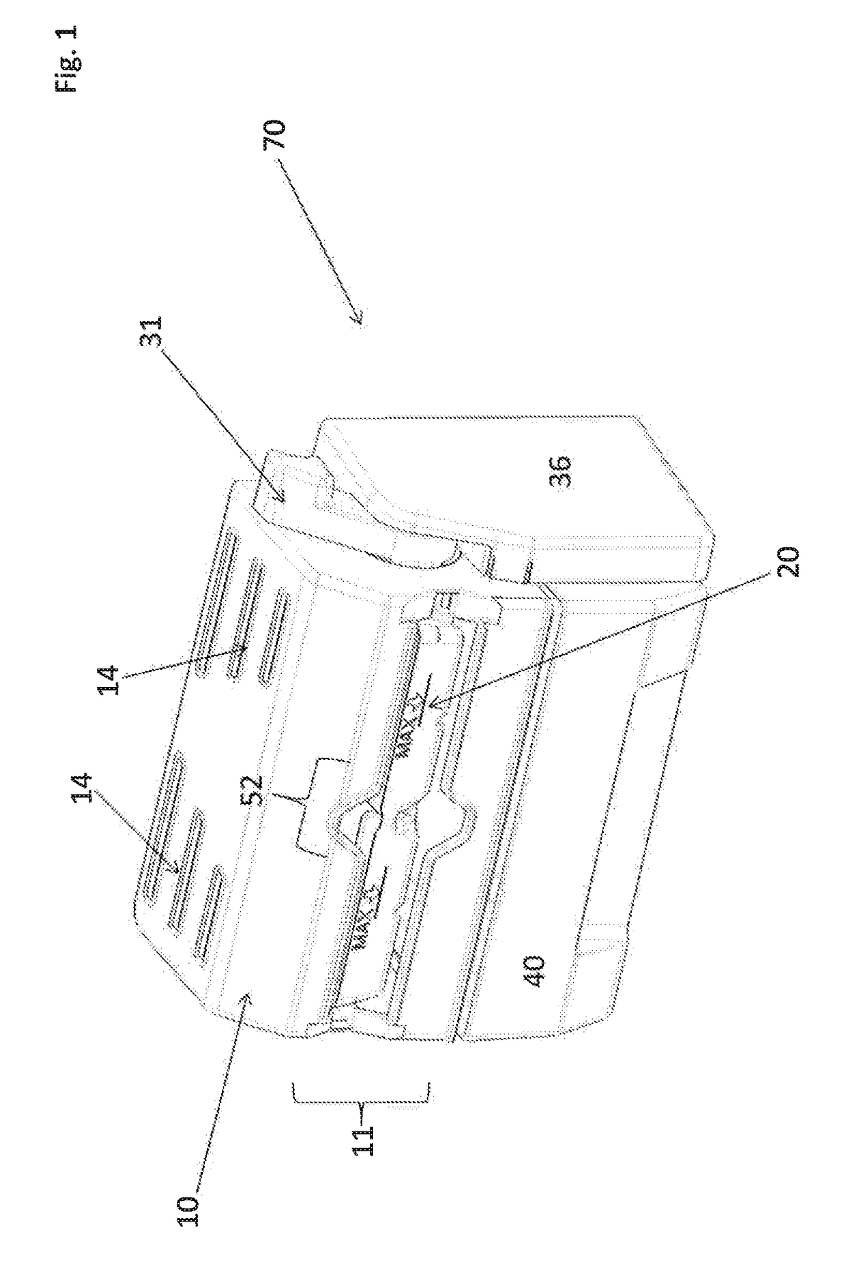
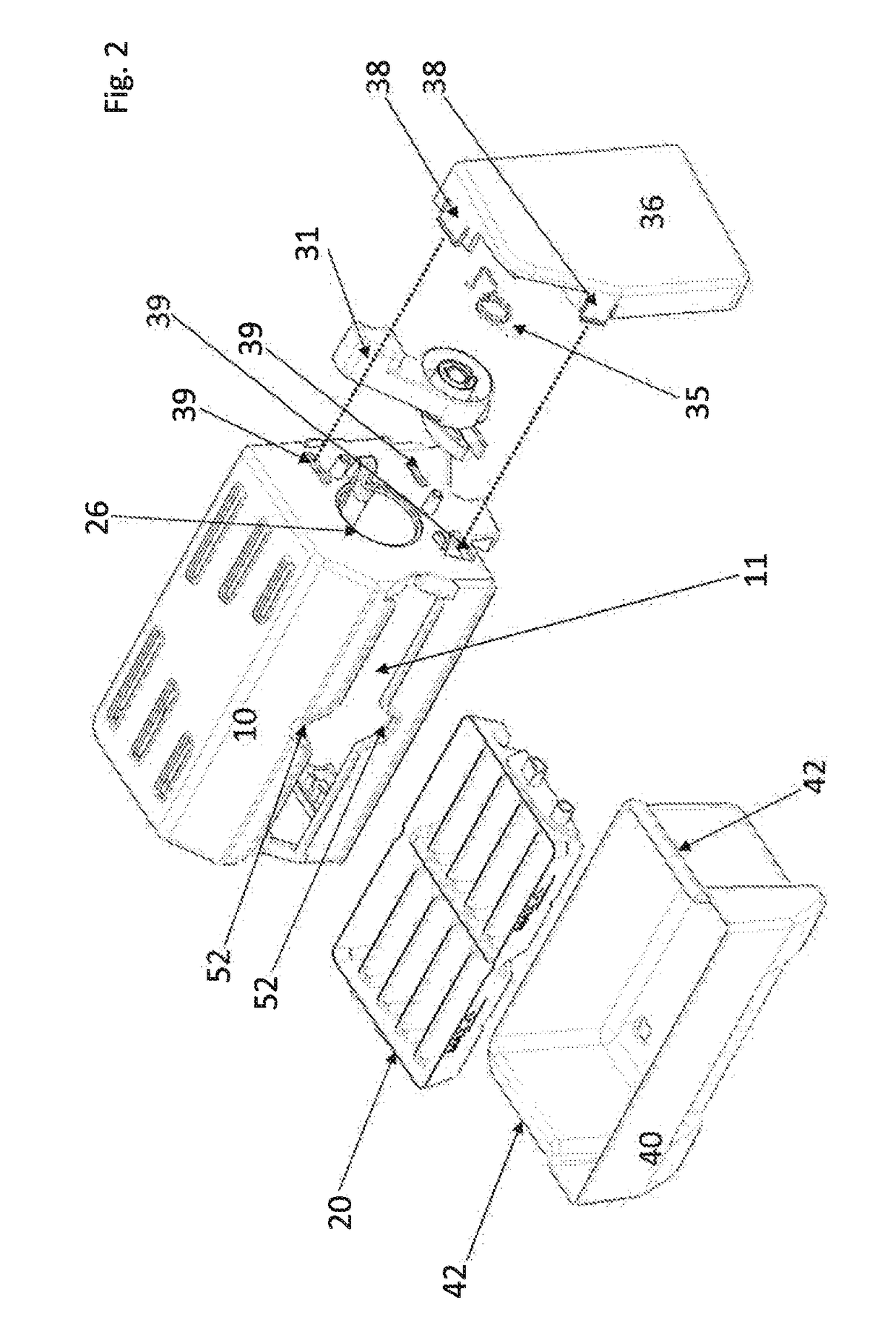
[0036]The present invention relates to an ice making device which is designed to be mounted in a separable manner on the inner cover or “liner” (46) of a freezer compartment of a household refrigerator. More specifically, it relates to an ice making device of the type having a removable ice tray for containing water in order to form ice bars.

[0037]As is shown in FIGS. 1 through 12b the ice bar making device (70) is constituted by a series of main elements coupled between them and which interact effectively in order to carry out the function of the same, such as explained below.

[0038]Initially it has a main carcass structure (10) (illustrated in FIG. 3) which in a preferable manner has a substantially parallelepiped shape, and which functions as the main structure for support for the entire ice bar making device (70). Said main carcass structure (10) may be manufactured with any adequate rigid polymeric material, such as polycarbonate, polyethylene, polystyrene, etc. Additionally, in...


PUM


Abstract

A device for making ice bars set within a freezer of a household refrigerator, the device comprising a carcass with a lateral face, an opposite lateral face, a neck in “V” shape, the lateral faces and a guiding throat which tops off with a semi-cylinder which is in connection with a “C” channel set over the opposite lateral face; a lever set over a runway found on the lateral face of the carcass, wherein said lever is mechanically grasped to a helicoid spring which returns it to its resting position, the lever comprising a disk and a “U” channel set over the disk and a pair of cylindrical concentric walls which form a cavity which houses the helicoid spring; a guard set over the lateral face of the carcass which contains the lever, the guard has an inner face; wherein said guard has a protruded tube in its inner face which is housed within the inner cylindrical wall of the lever; a tray which houses a series of molds for making ice bars, which on its flank sides has set on it a central axis portion and a cam follower; and a drawer for collecting the ice bars produced and extracted from the tray upon turning it and deforming it, when the user takes the lever to its final resting position on the runway.

Description

CROSS-REFERENCE TO RELATED APPLICATIONS[0001]This application claims priority to Mexican Patent Application No. MX / a / 20141002590 filed Mar. 4, 2014, and incorporated herein by reference in its entirety.BACKGROUND OF THE INVENTION[0002]The present invention relates to an ice making device. Said ice making device is designed to be mounted in a removable manner within a freezer compartment of a household refrigerator. More specifically, it relates to an ice making device of the kind which has a rotating ice making tray which is also extractable by means of a rotation transmission mechanism.PRIOR ART DESCRIPTION[0003]Ice making devices are usually mounted within a freezer compartment in a typical refrigerator with the end goal of easing the manufacture and dispensation of the same. In the state of the art, trays or molds for ice are found which can be rotated in order to empty the ice cubes formed within them by means of simple independent knobs coupled unto each of the same. Currently,...

Claims


Application Information

Patent Timeline
Patent Type & Authority Patents(United States)
IPC IPC(8): F25C5/18F25C1/24F25C5/04
CPCF25C5/04F25C1/24
Inventor CAMACHO VELAZQUEZ, ALAN FEDERICO
Owner MABE SA DE CV
Why Eureka
Try Eureka