Storage battery apparatus

a storage battery and battery technology, applied in the direction of light to electrical conversion, temperature-sensitive devices, cell components, etc., can solve the problem that the temperature detection unit can be diagnosed as abnormal, and achieve the effect of reliable electric power apparatus

Active Publication Date: 2017-08-29
HITACHI ASTEMO LTD
View PDF22 Cites 2 Cited by
  • Summary
  • Abstract
  • Description
  • Claims
  • Application Information

AI Technical Summary

Benefits of technology

[0012]When the battery module includes plural batteries, the temperature detection units are also disposed at the plural batteries. If there are some variations between the values detected by the temperature detection units disposed at the plural batteries, and also the difference of the variations exceeds a certain threshold, the cooling unit is caused to operate. Thereby, the temperatures of the plural batteries are equalized, so that the accuracy of the present invention is improved.
[0013]When an input and output control apparatus is provided which limits input and output of the battery module, and the control unit diagnoses the abnormality of the temperature detection units or the cooling unit, the input and output control apparatus limits the input and output of the battery module to such a value that it can be safely used even if the cooling unit does not operate. Thereby, a highly reliable storage battery apparatus can be realized which can operate an electric power apparatus even if the abnormality is detected.
[0016]According to the present invention, it becomes possible to diagnose not only the status of the cooling unit but also the status of the temperature detection unit, and to realize a highly reliable electric power apparatus.

Problems solved by technology

Moreover, the temperature of the outputting cooling medium is lower than the temperature of the inputting cooling medium, the temperature detection units can be diagnosed as abnormal.

Method used


Image

  • Storage battery apparatus
  • Storage battery apparatus
  • Storage battery apparatus

Examples


exemplary embodiment 1

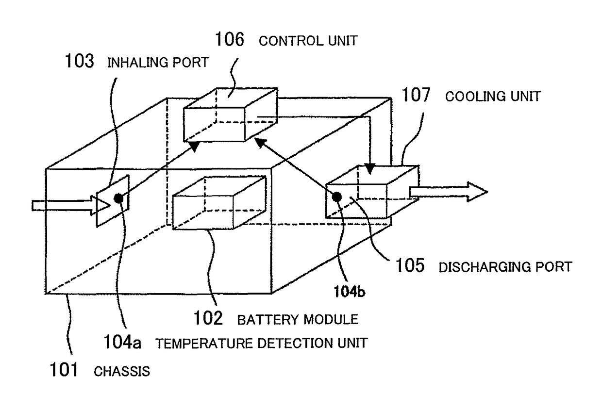
[0027]FIG. 1 is a diagram illustrating exemplary embodiment 1 according to the present invention. In FIG. 1, reference numeral 101 denotes a chassis, reference numeral 102 denotes a battery module, reference numeral 103 denotes a inhaling port, reference numerals 104a and 104b designate temperature detection units, reference numeral 105 denotes a discharging port, reference numeral 106 denotes a control unit, and reference numeral 107 denotes a cooling unit.

[0028]The chassis 101 encloses the battery module 102. The inhaling port 103 and the discharging port 105 are disposed on this chassis 101, and the temperature detection units 104a and 104b are disposed around the inhaling port 103 and the discharging port 105. The cooling unit 107 is disposed at the discharging port 105. The temperature detection units 104a, 104b, and the cooling unit 107 are electrically connected to the control unit 106.

[0029]The battery module 102 is configured to connect one or plural batteries such as a lit...

exemplary embodiment 2

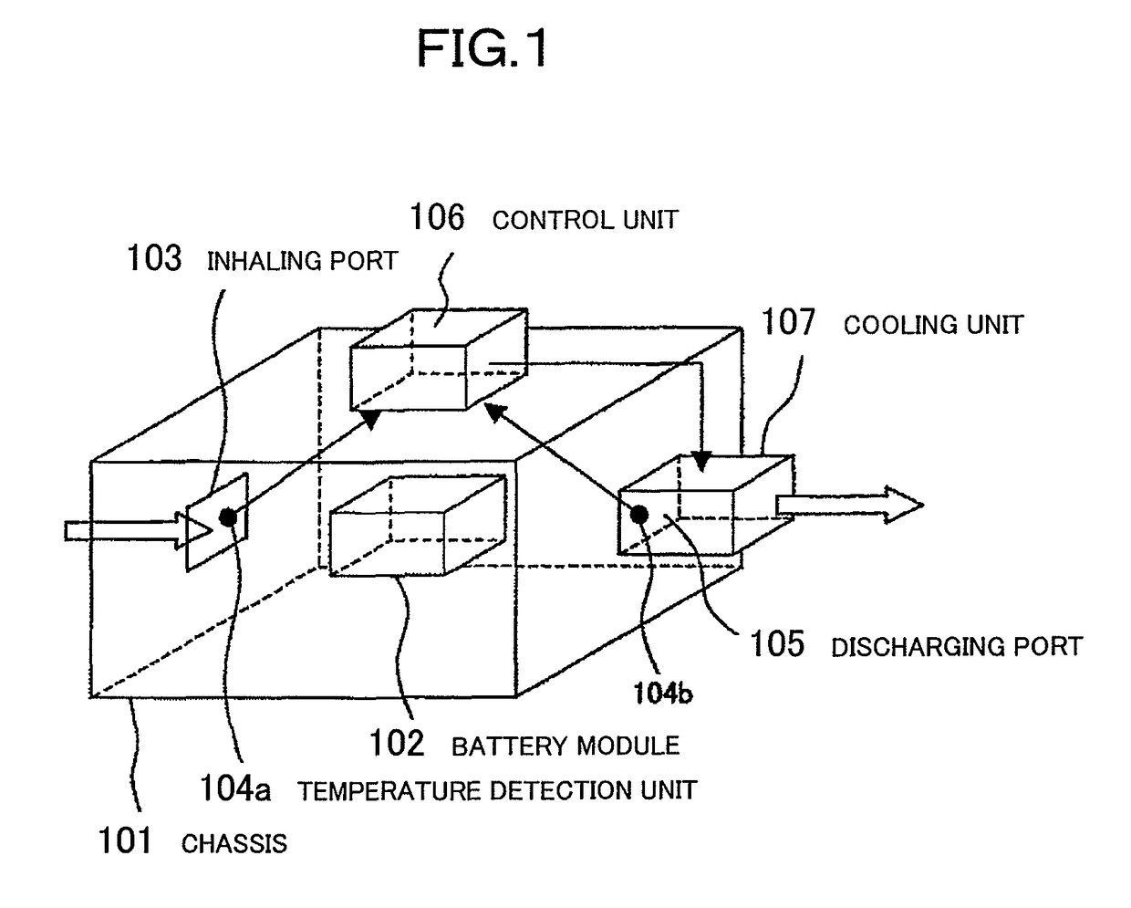
[0037]FIG. 2 is a diagram illustrating exemplary embodiment 2 according to the present invention. In FIG. 2, reference numeral 201 denotes a battery, reference numeral 202 denotes a current detection unit, reference numeral 203 denotes a voltage detection unit, reference numerals 104a, 104b (inhaling / discharging temperature of cooling medium), 102a (temperature of battery module), and 204a, 204b (temperature of battery) denote temperature detection units, reference numeral 205 denotes a selection unit, reference numeral 206 denotes a microcomputer, and reference numeral 207 denotes a communication unit.

[0038]Plural batteries 201 are connected in series, and configure a battery module. Moreover, the control unit 106 is configured with the voltage detection unit 203, the selection unit 205, the microcomputer 206, and the communication unit 207.

[0039]The current detection unit 202 is disposed at the battery module 102, and its output is inputted to the microcomputer 206. In addition, t...

exemplary embodiment 3

[0073]FIG. 7 is a diagram illustrating exemplary embodiment 3 according to the present invention, and illustrating an exemplary embodiment of an electric power supply for a hybrid electric vehicle to which an exemplary embodiment of an electric power apparatus according to the present invention is applied. In FIG. 7, reference numeral 501 denotes an engine, reference numeral 502 denotes a power dividing transmission mechanism, reference numeral 503 denotes a motor, reference numeral 504 denotes an inverter, reference numeral 505 denotes a system controller, reference numeral 506 denotes a reporting unit, reference numerals 507a and 507b denote driving wheels, and reference numeral 508 denotes a drive shaft.

[0074]The engine 501 is connected with the motor 503, and the driving wheels 507a and 507b through the power dividing transmission mechanism 502 and the drive shaft 508, and so-called a parallel hybrid electric vehicle is configured in which the driving wheels 507a and 507b are dr...


PUM

PropertyMeasurementUnit
temperatureaaaaaaaaaa
temperaturesaaaaaaaaaa
electric poweraaaaaaaaaa

Abstract

There is provided a highly reliable storage battery apparatus which can diagnose the status of a temperature detection unit and a cooling unit. In the storage battery apparatus comprising a battery module including one or more batteries, a plurality of temperature detection units and a cooling unit cooling the battery module, the temperature detection units measure, at least, the temperature of the cooling medium inputted to the storage battery apparatus, the temperature of the cooling medium outputted from the storage battery apparatus, and the temperature of at least one of the batteries and the battery module.

Description

BACKGROUND OF THE INVENTION[0001]Field of the Invention[0002]The present invention relates to a storage battery apparatus including a battery such as a lithium secondary battery, a lead battery, a nickel-hydrogen battery, and an electric double layer capacitor, and an electric power apparatus, a distributed electric power storage apparatus, and a hybrid electric vehicle which mount such storage battery apparatus.[0003]Background Art[0004]Because of the gas emission regulation and improvement of fuel consumption, a hybrid electric vehicle has been actively developed which uses a secondary battery as an auxiliary assist power for an engine. A lithium secondary battery and a nickel-hydrogen battery have been often used as this secondary battery for a vehicle. A secondary battery used as a battery of a hybrid electric vehicle is used for assist of an engine (assist in case of acceleration), and supplies electric power to a motor in case that the vehicle is driven only with the motor on ...

Claims


Application Information

Patent Timeline
Patent Type & Authority Patents(United States)
IPC IPC(8): H01M2/10H01M10/63H01M10/61H01M10/60B60L11/18H01M10/613H01M10/633B60L11/14H01M10/48B60L3/00B60L8/00H01M10/6566H01M10/6567H01M10/6563H01M10/656H01G2/08B60K6/28B60K6/44B60K6/485B60L50/16H01G9/21H01G9/26H01M50/213H02J7/00
CPCH01M2/1072B60L3/0046B60L8/003B60L11/14B60L11/187B60L11/1874B60L11/1879H01M10/486H01M10/60H01M10/61H01M10/613H01M10/63H01M10/633B60L2240/545H01M10/656H01M10/6563H01M10/6566H01M10/6567Y02T10/70Y02T10/705Y02T10/7005Y02T10/7077Y02T10/7083B60L50/16B60L58/24B60L58/26B60L50/64B60L58/18Y02T10/7072Y02E60/10H01M50/213
Inventor EMORI, AKIHIKOKAWAHARA, YOUHEIKAWATA, TAKAHIROKUDO, AKIHIKO
Owner HITACHI ASTEMO LTD
Why Eureka
Try Eureka