Apparatus having self healing liquid phase power connects and method thereof

Active Publication Date: 2017-08-08
WOLFSPEED INC
View PDF47 Cites 3 Cited by
  • Summary
  • Abstract
  • Description
  • Claims
  • Application Information

AI Technical Summary

Benefits of technology

The present invention is about a new type of power connector that can change from liquid to solid and back again to relieve stresses caused by temperature changes. This interconnect is perfect for high-temperature and reliable operation for long periods of time. It is an ultra-low inductance liquid metal connector that reduces interconnect inductance and enables multi-directional cooling, which increases the current and power density of power modules. Additionally, this new technology can improve the reliability of power electronics up to 20 years. It can be used with various semiconductor switch technologies. Overall, this invention provides a simple, low-cost solution to extend the life of power electronics and enable continued operation under extreme environments and conditions.

Problems solved by technology

Typical circuit or chip packages use wire bond interconnects which is one of the main limitations of today's state-of-the-art power interconnects.
Wire bond interconnects introduce major inductance parasitics into the power flow; severely limiting switching frequencies, causing di / dt and dv / dt overcurrent and overvoltage waveforms within the power modules, and causing substantial bus ringing that must be minimized via bulky DC-link capacitors.
Such electrical issues at the switch and module level magnify stresses across the power transistor, negatively impacting long term reliability of the semiconductor.
These wire bonds are highly susceptible to mechanical fatigue failure as the packaging undergoes thermal and power cycling because the wires become stressed at the substrate interface, die interface, bond heel, and bond knee, all of which become potential points for fracture and failure.
This often results in substantial current crowding at the knee or heel of the bond, and at the die-pad interface which again, results in potential points of failure due to localized hot spots and stresses.
All of these issues become further exacerbated with the transition to wide bandgap power devices, which are capable of high temperature operations well in excess of 250° C. and these limitations severely limit the 600+° C. that is theoretically achievable.
Such wire bond interconnects will clearly have difficulty achieving long term confidence and reliability in wide bandgap power systems, and even in today's low temperature silicon based systems they cannot achieve the 10+ year reliability targets set out by the department of energy for many industry platforms (automotive, solid-state smart grid, etc.).
These processing techniques have barely penetrated into the power switch market, primarily due to the fact that power devices (unlike high frequency ICs) are vertical devices requiring both top-side and backside electrical connections.
Flipping the device still leaves the power transistor backside exposed and requiring an electrical connection.
Developers have shown metal tabs, straps, and solder contacts all to be feasible for this top-side contact, but they suffer from reliability problems on par with or worse than wire bonding.
It simply is not achievable for today's commercial high voltage power modules to operate at significantly high switching speeds or frequencies.
The energy losses in the power module parasitics are too high, and this in turn limits the capability of the entire power electronic converter system.
With the introduction of advanced wide bandgap materials, today's power modules cannot achieve the junction temperatures conducive to taking full advantage of the thermal performance of these new devices.
Finally, present power packaging technologies will not survive the new long term reliability requirements demanded by newer fields like automotive and smart grid, which absolutely must deliver reliable service to their customers at all times. It is critical that new investments be made, now, into revolutionary power packaging ideas that can overcome many of these debilitating weaknesses, or smart power electronics will remain elusive.
From these prior references it may be seen that the prior art is very limited in its teaching and utilization, and an improved connection is needed to overcome these limitations.

Method used


Image

  • Apparatus having self healing liquid phase power connects and method thereof
  • Apparatus having self healing liquid phase power connects and method thereof
  • Apparatus having self healing liquid phase power connects and method thereof

Examples


Embodiment Construction

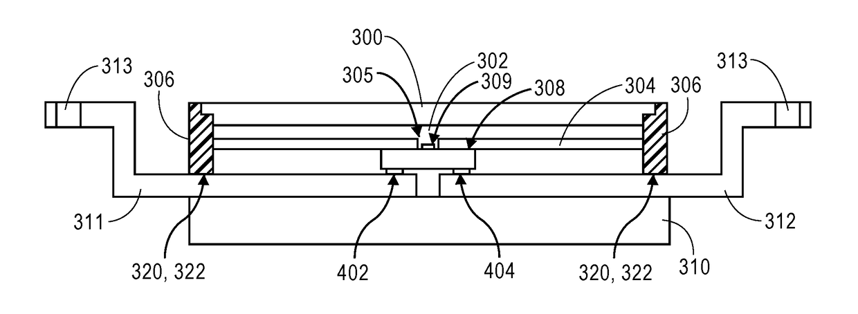
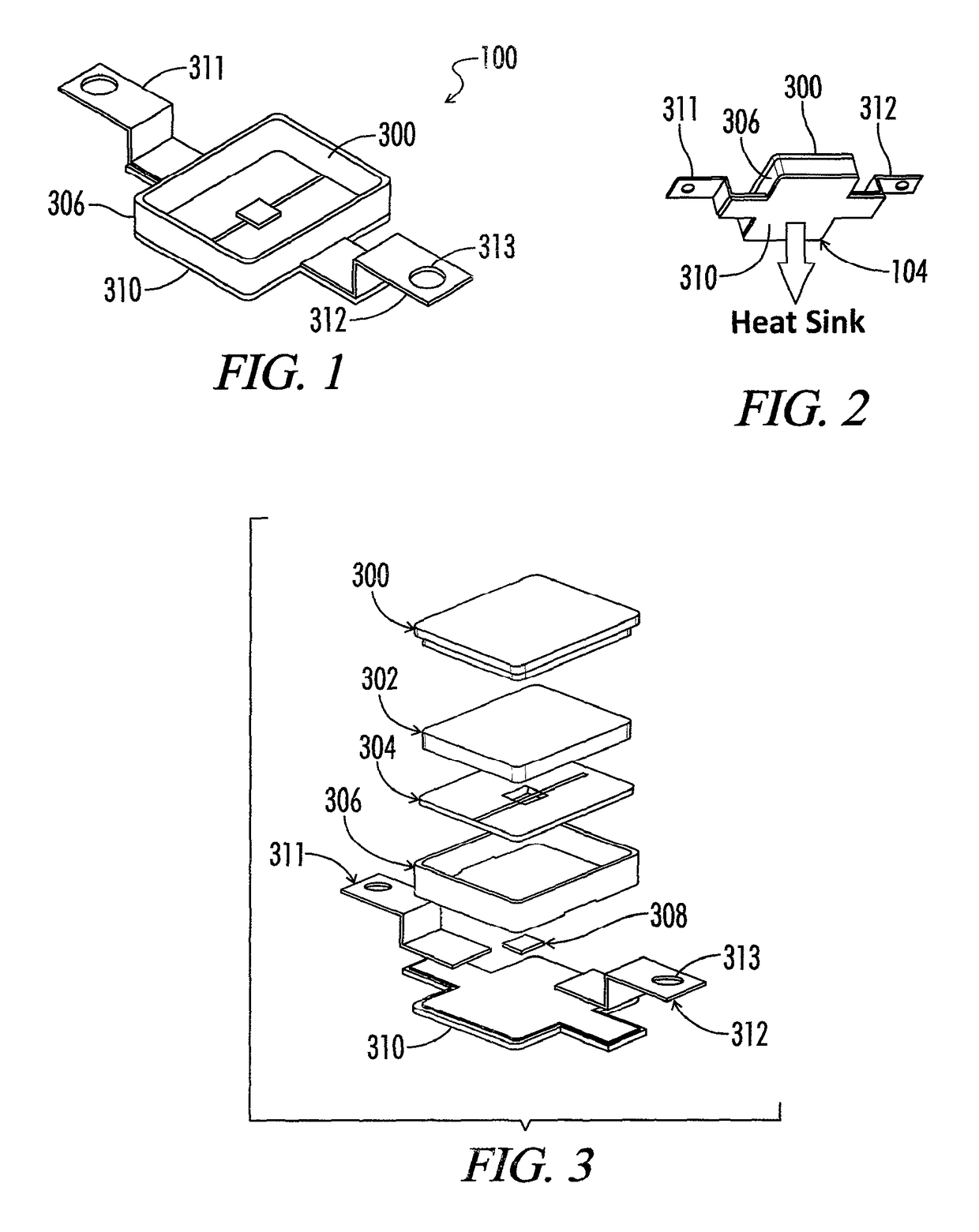
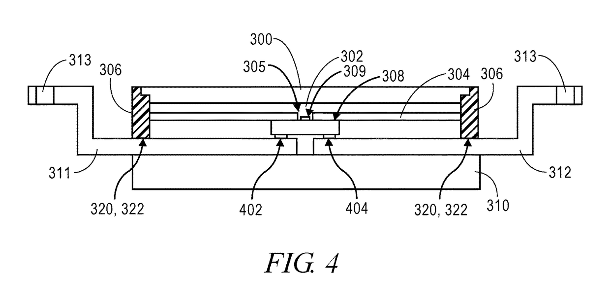
[0022]The preferred embodiment of the present invention is directed to a liquid phase power connect. As shown in FIGS. 1, 2, 3 and 4 of the drawings this system uses a fundamentally revolutionary concept in which the wire bond (or other topside) interconnect is replaced with a liquid metal in such a manner as to make an ultra high reliability electrical connection between the power transistor and the package power lead. This may be utilized in any number of package designs, from simple discrete packaged diodes, discrete packaged transistors and paralleled transistor switch positions, through and including full power modules (such as a half-bridge). For discussion purposes, the concept is illustrated in FIGS. 1 through 4 as a discretely packaged surface mount component 100 housing a three-terminal power transistor shown as a MOSFET 308.

[0023]The power MOSFET 308 electrical device is mounted onto the isolated power substrate 310 in a flip-chip fashion, with the gate pad 402 and source...


PUM


Abstract

The present invention is directed to a liquid and solid phase power connect for packaging of an electrical device using a using a phase changing metal. The phase changing metal transitions back and forth between a liquid phase and a solid phase while constantly maintaining connection to the electrical device. The packaging uses a substrate, a restraining housing, and a lid to encase an electrical contact on the electrical device and restrain the phase changing metal. In one embodiment, the entire electrical device is encased and a voltage isolator is utilized to limit the contact areas between the phase changing metal and the electrical device. A method for relieving contact stress by transitioning the phase changing metal from a solid to a liquid is also taught.

Description

CROSS-REFERENCE TO RELATED APPLICATIONS[0001]This application claims priority to and is a continuation in part of U.S. patent application Ser. No. 13 / 068,232 filed May 5, 2011 by Losteller entitled Self Healing Liquid Phase Power Connects, which was a continuation in part of and claimed priority to U.S. Provisional Application 61 / 343,881, filed May 5, 2010 by Lostetter of Fayetteville, Ark. entitled Self Healing Liquid Phase Power Connects.STATEMENT REGARDING FEDERALLY SPONSORED RESEARCH OR DEVELOPMENT[0002]Not Applicable.REFERENCE TO A MICROFICHE APPENDIX[0003]Not Applicable.RESERVATION OF RIGHTS[0004]A portion of the disclosure of this patent document contains material which is subject to intellectual property rights such as but not limited to copyright, trademark, and / or trade dress protection. The owner has no objection to the facsimile reproduction by anyone of the patent document or the patent disclosure as it appears in the Patent and Trademark Office patent files or records ...

Claims


Application Information

Patent Timeline
IPC IPC(8): H05K7/00H05K1/18H05K1/02H05K13/00H01R12/52
CPCH01R12/52H05K1/0271H05K1/181H05K13/00H05K2201/068H05K2201/10954H01L23/057H01L23/24H01L23/4275H01L2224/16245H01L2924/13091H01L2224/73253H01L2224/32245H01L2224/29305H01L2224/29311H01L2224/29309H01L2224/29313H01L24/29H01L24/32H01L2924/014H01L2924/01049H01L2924/0105H01L2924/01031H01L2924/01083H01L24/00
Inventor LOSTETTER, ALEXANDER
Owner WOLFSPEED INC
Why Eureka
Try Eureka