
Mammography method and apparatus to generate an X-ray tomosynthesis image of a breast of a patient

a tomosynthesis image and breast technology, applied in the direction of patient positioning for diagnostics, instruments, applications, etc., can solve the problems of inability to reliably produce the aforementioned composite image, the projection angle of the first tomosynthesis scan deviating slightly, and the patient's dose exposure is reduced, so as to achieve the effect of reducing the dose exposure of the patient and reducing the quality of the diagnosis

Active Publication Date: 2017-08-08
SIEMENS HEALTHCARE GMBH
View PDF4 Cites 4 Cited by
  • Summary
  • Abstract
  • Description
  • Claims
  • Application Information

AI Technical Summary

Benefits of technology

[0009]The invention thus largely eliminates the aforementioned disadvantages that conventionally occur with a weighted subtraction in the projection domain, without it being necessary to stop the mammography apparatus that is used to generate the projection images at the individual angle positions and to conduct the acquisitions with different x-ray energies at this stopped position.
[0010]In this way it is possible to initially implement a complete tomosynthesis scan with a first x-ray energy with continuous movement of the x-ray tube, followed by a complete tomosynthesis scan implemented with a second x-ray energy. In other words: all first digital projection images can be acquired before or after the acquisition of all second digital projection images.
[0011]Is likewise possible to implement one of the two tomosynthesis scans (preferably the tomosynthesis scan implemented with low-energy x-rays) with a reduced number of angle positions in order to lower the dose exposure of the patient in this way without the quality of the diagnosis therefore being reduced, since dose is primarily based on achieving visibility of the injected contrast agent. In other words: it is possible for the first number of first projection images to be smaller than the second number of second projection images.

Problems solved by technology

However, in the known procedure it is disadvantageous that slice images that are already plagued with a loss of information (due to the calculation steps taken within the scope of the tomosynthetic reconstruction, for example the use of spectral filters and the dynamic compression given filtered back-projection) are used for the weighted subtraction.
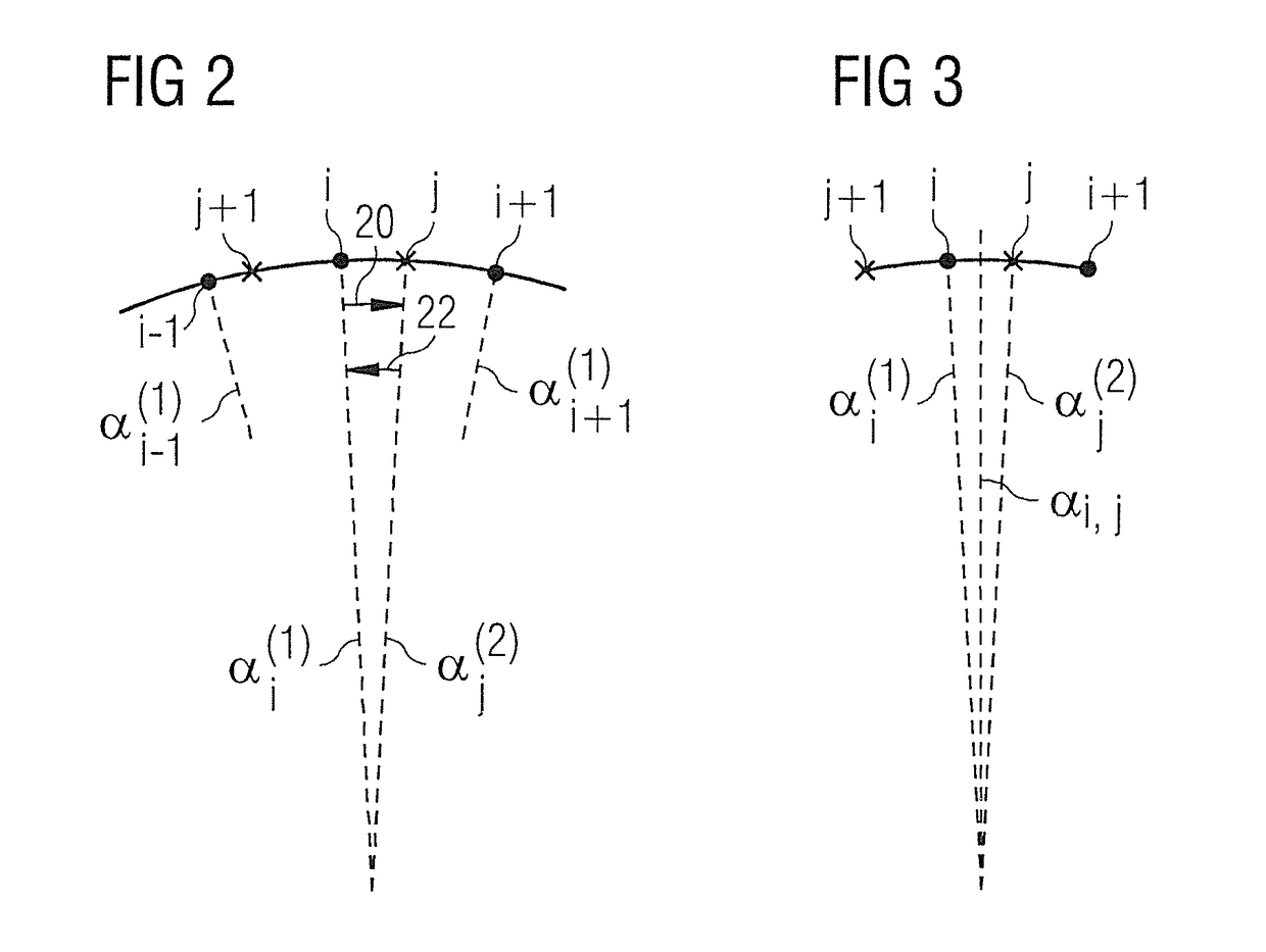
However, a problem with such a procedure is that the tomosynthesis scan is implemented during a continuous pivot motion of the x-ray tube, such that the projection angles of the first tomosynthesis scan deviate slightly in practice from the projection angles of the second tomosynthesis scan, due to unavoidable tolerances (mechanism, pulse time, timing of the x-ray detector).
Thus, in practice, it is not possible to reliably produce the aforementioned composite image by a subtraction of two images respectively acquired at precisely the same projection angle.

Method used


Image

  • Mammography method and apparatus to generate an X-ray tomosynthesis image of a breast of a patient
  • Mammography method and apparatus to generate an X-ray tomosynthesis image of a breast of a patient
  • Mammography method and apparatus to generate an X-ray tomosynthesis image of a breast of a patient

Examples


Embodiment Construction

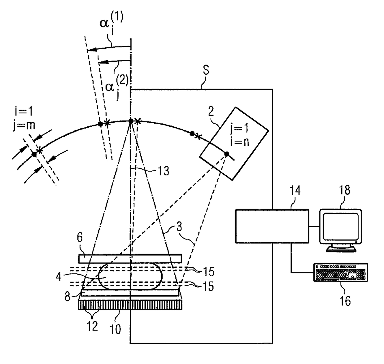
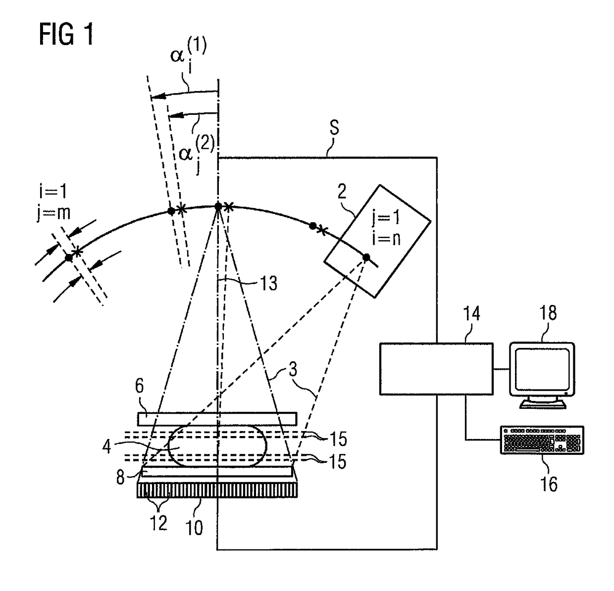
[0020]As shown in FIG. 1, the mammography apparatus has an x-ray tube 2 to generate x-rays 3 that traverse the breast 4 of a patient that is embedded between a compression plate 6 and a support plate 8. The x-rays 3 traversing the breast 4, the compression plate 6 and the support plate 8 are received by a large-area digital x-ray detector 10 that is made up of a plurality of individual detectors 12 arranged in a matrix-like array. The x-ray source 2 can move into different first and second angle positions i=1 through n and j=1 through m—in the example it is pivoted—so that first and second projection images p(1)i, p(2)j of the examination subject 4 can be generated with different first and second projection angles α(1)i, α(2)j relative to the normal 13 of the support plate 8 of the x-ray detector 10. In FIG. 1, the angle positions of the foci from which the x-rays 3 emanate are respectively drawn for different projection angles.

[0021]In the first angle positions i, the x-ray tube 2 ...


PUM


Abstract

In a mammography method and apparatus to generate a tomosynthetic x-ray image of a breast of a patient, two tomosynthesis scans are successively implemented with different x-ray energies. In one of the scans, a synthetic projection image is generated from at least two projection images acquired in this scan, this synthetic projection image corresponding to a projection at a projection angle at which a projection image has been acquired in the other scan. A difference image, used to reconstruct the tomosynthesis x-ray image, is generated from this synthetic projection image and the projection image acquired in the other scan. Alternatively, in each scan a synthetic projection image is generated from at least two projection images acquired in that scan. Each synthetic projection image represents a projection at the same projection angle. A difference image, used to reconstruct the tomosynthesis x-ray image, is generated from these two synthetic projection images.

Description

BACKGROUND OF THE INVENTION[0001]Field of the Invention[0002]The present invention concerns a method to generate a tomosynthetic x-ray image of a breast of a patient, as well as a mammography apparatus operated with such a method.[0003]Description of the Prior Art[0004]Tomosynthesis is an imaging modality in which projection images (projection data sets) of an examination subject are acquired with a digital x-ray detector at a number of different projection directions. By known image reconstruction methods, a three-dimensional image data set can be generated from these digital projection images acquired from different projection directions or projection angles in a limited angle range (for example between −25° and +25° relative of the acquisition area of the x-ray detector), i.e. from the image data representing these projection images, this three-dimensional image data set is compose of a number of slice images that each depict a subject slice oriented parallel to the acquisition a...

Claims


Application Information

Patent Timeline
Patent Type & Authority Patents(United States)
IPC IPC(8): A61B6/02A61B6/00G06T11/00A61B6/04
CPCA61B6/025A61B6/482A61B6/502A61B6/5205G06T11/006A61B6/0414G06T2211/436
Inventor HORNIG, MATHIAS
Owner SIEMENS HEALTHCARE GMBH
Learn More