
Electronic tool and methods for meetings

a technology of electronic tools and meetings, applied in the field of electronic tools and methods for meetings, to achieve the effect of reducing the footprint of termination and making meetings more effective and efficien

Active Publication Date: 2017-08-01
BARCO NV
View PDF55 Cites 23 Cited by
  • Summary
  • Abstract
  • Description
  • Claims
  • Application Information

AI Technical Summary

Benefits of technology

[0042]Obtaining user selected arbitrary media content is preferably not obtained by application sharing but by the process of screen scrapping. Although software packages that provide screen scraping require installation on the target device, or at least require the installation of dedicated and / or custom drivers, embodiments of the present invention use software loaded onto the peripheral device which allows screen scraping when run on the processing device but leaves a zero footprint when terminated. Embodiments of the present invention can screen scrape full HD videos at 20 fps without requiring any installation of a program on the processing device nor requiring configuring the processing device such as a PC that they run on for the connectivity to the network hence meeting “zero footprint” requirements.
[0046]Embodiments of the present invention “auto compose” arbitrary user data on a central display or screen so that full real-time content that is provided by multiple meeting participants who intentionally share this content in order to make the meeting more effective and efficient,
[0082]“Plug and play” is a term used to describe the characteristic of a computer bus, or device specification, which facilitates the discovery of a hardware component in a system, without the need for physical device configuration, or user intervention in resolving resource conflicts. Plug and play devices can be added to a bus of a computing system (while running or when shut down), and the newly added device and possibly the rest of the computing system is automatically configured to make the newly added device work, both from hardware and from software perspective.

Problems solved by technology

Unfortunately, for many information managers, being in perpetual meetings has reduced their ability to prepare adequately for the next meeting, perpetuating a vicious and negative cycle.
However, Marc Al-Hames et al. report in “Audio-Visual Processing in Meetings: Seven Questions and Current AMI Answers”, that although large parts of working days are consumed by meetings and conferences, unfortunately a lot of them are neither efficient, nor especially successful.
The conclusion is that despite the plethora of electronic aids to meetings, fundamental problems in handling meetings have not been solved.
This article addresses the issue that the lack of direct feedback makes meetings clumsy, inefficient and often unproductive.
It is argued that interrupting a presenter in full flow can be awkward; however, sometimes it is difficult to get an opportunity to ask a question or make a comment when many different people are trying to make their voices heard.
Hence, these proposals still leave a central figure such as the presenter in a dominating position and the other members of the meeting are largely an audience with limited selection or voting or participation rights.
A further problem with meetings is that someone is usually late or has to leave early.
Presents systems do not provide an optimal solution.
In addition, connecting to a network brings the danger of virus, malware or spyware transfer in either direction, and there is danger of copying of confidential information.
There are even more fundamental problems with using electronic tools in meetings.
This is not only not scalable but also can be and often is quite a cumbersome process that typically wastes valuable meeting time and takes the dynamism out of the meeting.
Connection can be made more difficult and time consuming for example if the computer has to be rebooted for it to detect the projector or when the format of the PC differs from the format of the projector.
In addition changing format can leave the computer with a new format that is not compatible with its own screen so that on reboot of the PC alone, nothing is displayed on the computer screen.
Without a visible screen image the necessary re-configuration can be difficult.
. . .Reach depends on cable length: too long leaves a tangled cable “salad” in the meeting room, too short reduces flexibility, often necessitating people to move around in the meeting room when they want to present something.Cable connection is either point to point or requires tedious and extensive cabling and the use of complex and expensive video switches.It is often difficult and time consuming to find the right display resolution and refresh rate that both the computer and the display or projector support.
If the connection is made to a corporate LAN there is a danger of virus, malware or spyware transfer in either direction, there is danger of copying of confidential information, and there is the difficulty of making the connection, e.g. entry of a user code and password, as well the administration of such passwords and user codes.
A drawback of method 3 is that the same problems often encountered with method 1 of connecting to the display adapter remain.
Another drawback is that the special device referred to requires significant processing power, which means that this device will consume much power, be relatively big and certainly be relatively expensive.
However, this usually requires special drivers and even special hardware.
Additional problems can occur with firewalls.
The setting up of a firewall can be complicated and if this is not done correctly, telecommunication software that has to pass through a firewall may be blocked.
Fussing with computer settings, or having to call for IT support wastes valuable meeting time and takes the dynamism out of the meeting.
The following problems remain for holding a face-to-face meeting using advanced electronic tools at the present time:Complexity of the networking infrastructure.High demands on technical expertise of users in current systems that are supposed to be designed to support everyday use by the non-expert user.Barriers to the use of complicated technology in meetings.Great variety of possible collaborative software solutions—none of which seems to solve the fundamental problems of holding successful meetings.Meetings being boring or annoying for members of the meeting.Complexity of firewalls and other security measures employed in corporate networks.Lack of, or restriction of participation by members of a meeting.Time taken to prepare presentations for meetings.Need to record events in the proper time sequence at meetings without burdening a meeting more than necessary.
Although some tools solve some of these problems effectively, no electronic meeting tool solves all of them.

Method used


Image

  • Electronic tool and methods for meetings
  • Electronic tool and methods for meetings
  • Electronic tool and methods for meetings

Examples


second embodiment

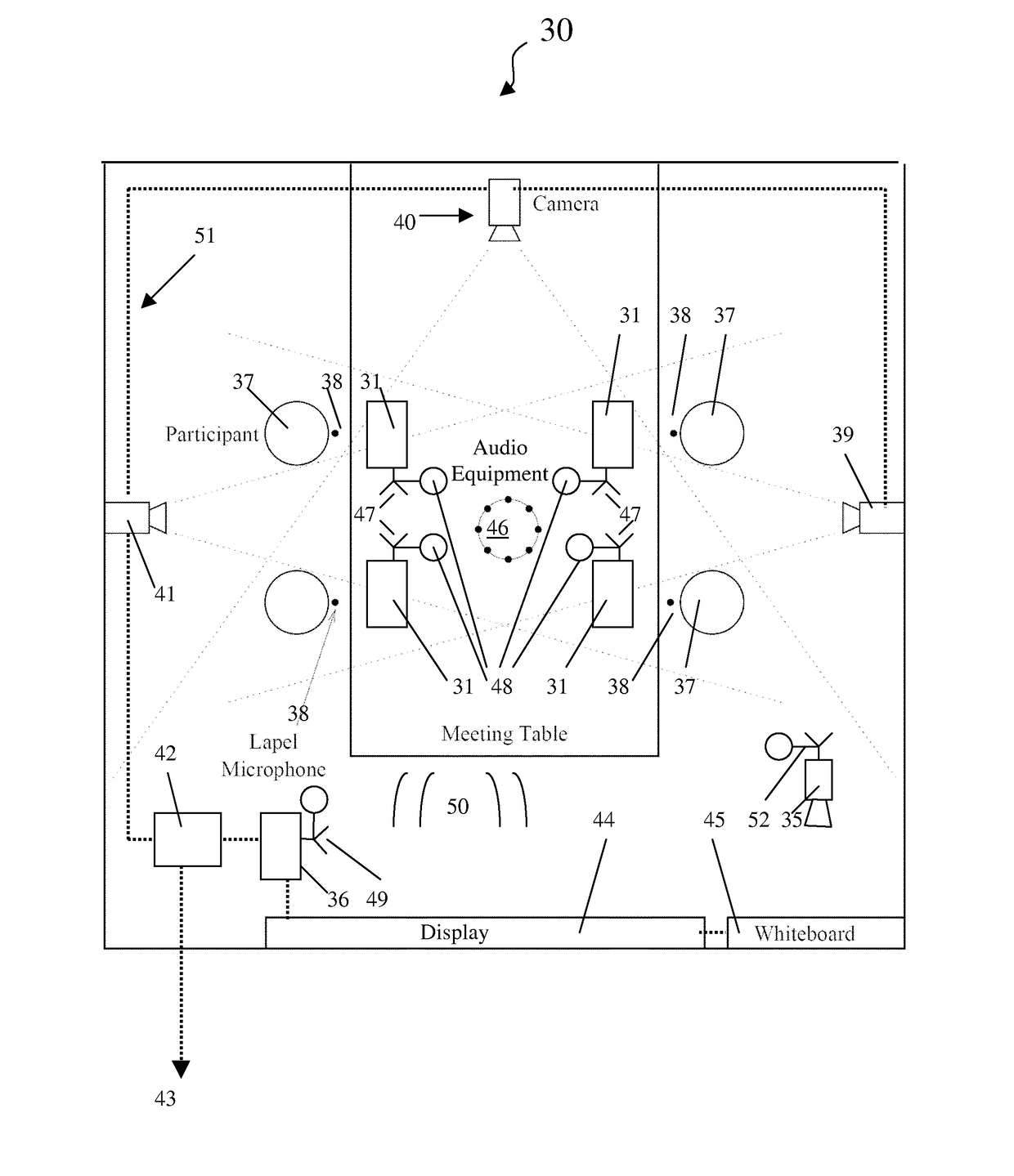
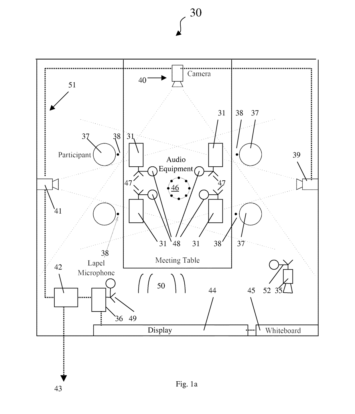
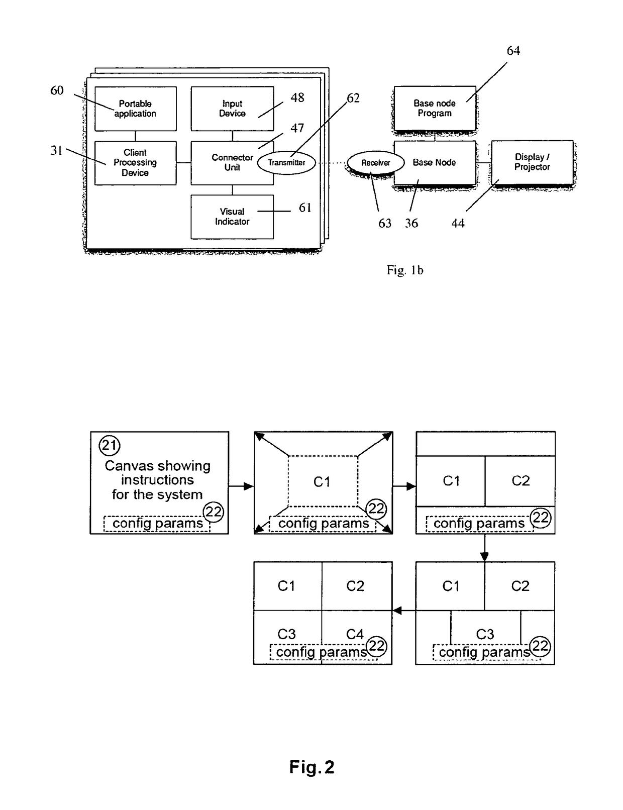
[0303]In the second embodiment, referring to FIGS. 2 to 5, the base node is a separate physical processing device called base unit (B), comprising permanent storage, memory, a processing engine, a wireless access point (4), a plug and play interface such as a USB port (11), a graphics display output adapter (5) like VGA / DP / DVI / HDMI, and optionally an audio output adapter (27). An input device having an actuator such as a button 13 and a visual indicator 14 are optional.

[0304]The connection unit is a physical device in the form of an external peripheral device (shown in the drawings as a “dongle” D) comprising permanent storage storing the portable application (7) and configuration parameters (12), memory, a processing engine (e.g. CPU, FPGA), a wireless transmitter such as WiFi (3), a plug and play interface such as a USB interface (2), a button as input device (9), an LED ring as visual indicator (10). The portable application is stored on the peripheral device (7).

[0305]The client...

third embodiment

tion Stored on Standard Solid State Memory Such as a USB Stick

[0324]In the third embodiment, the portable application is stored on a solid state memory such as a regular USB memory stick (FIG. 7).

[0325]With a solid state memory such as a regular USB memory stick, there is no input device, visual indicator or transmitter of the kinds described above for the connection unit. This means that the system needs to:[0326]Use the transmitter / receiver from the client processing device.[0327]Use as input device a key or button on the client processing device like a physical key on the keyboard, a special mouse press, a button area on a touch screen, a button displayed on the screen to be clicked on with a mouse pointer.[0328]Present the visual indicator on the client processing device's display.

[0329]The client processing device then looks like FIG. 8.

[0330]This embodiment provides a peripheral interface such as the USB interface on any processing device acting as a host device such as a comp...

fourth embodiment

ent Installed on the Client Processing Device

[0356]This embodiment is similar to the third embodiment, with as only difference that the software is copied on the client operating device (FIG. 9). In this case, no plug and play port such as a USB port is required on the client operating device.

[0357]This embodiment will typically be used for tablet PC's and mobile devices. In that case[0358]there is often no USB port available[0359]application distribution is easy and widely accepted through application stores


PUM


Abstract

An electronic meeting tool and method for communicating arbitrary media content from users at a meeting. These can include a node configuration device adapted to operate a display node of a communications network, the display node being coupled to a first display. The node configuration device is adapted to receive user selected arbitrary media content and to control display of the user selected arbitrary media content on the first display. At least one peripheral device adapted to communicate the user selected arbitrary media content via the communications network is provided, where the peripheral device is a connection unit including: (e) a connector adapted to couple to a port of a processing device having a second display, a memory and an operating system; and (f) a transmitter for communicating with the communications network.

Description

[0001]The present invention relates to electronic tools for meetings including methods or devices for providing connection to a communications network, to networks or methods of operating the network, methods or devices for use in displaying media content as well as software for performing any of these methods.TECHNICAL BACKGROUNDTools for Collaboration[0002]Allowing ad hoc groups of persons to communicate with each other is one of the fundamental aspects of collaboration, problem solving, negotiation, teaching and education, etc. To assist in communication, there has been an explosion of electronic communication tools such as electronic conferencing tools, e.g. synchronous and asynchronous conferencing, online chat, Instant Messaging, audio conferencing, videoconferencing, data conferencing, application sharing, remote desktop sharing, electronic meeting systems, collaborative management (coordination) tools, project management systems, knowledge management systems, and social soft...

Claims


Application Information

Patent Timeline
Patent Type & Authority Patents(United States)
IPC IPC(8): G06F15/16H04L29/06H04L12/18
CPCH04L63/08H04L12/1818H04L65/403H04L12/1822H04L12/1827H04N7/15H04L65/4046
Inventor BRANDS, JOHANNES WILLEMDEWAELE, RONNY RUDY
Owner BARCO NV
Learn More