
Methods and systems for calibration of voltage regulator systems with multiple types of power stages

a voltage regulator and power stage technology, applied in the field of information handling systems, can solve problems such as jeopardizing the implementation of pcb layout optimization, and achieve the effects of improving the accuracy of current sense, power saving and reliability, and reducing or substantially eliminating continuity of supply concerns

Active Publication Date: 2017-06-13
DELL PROD LP
View PDF24 Cites 5 Cited by
  • Summary
  • Abstract
  • Description
  • Claims
  • Application Information

AI Technical Summary

Benefits of technology

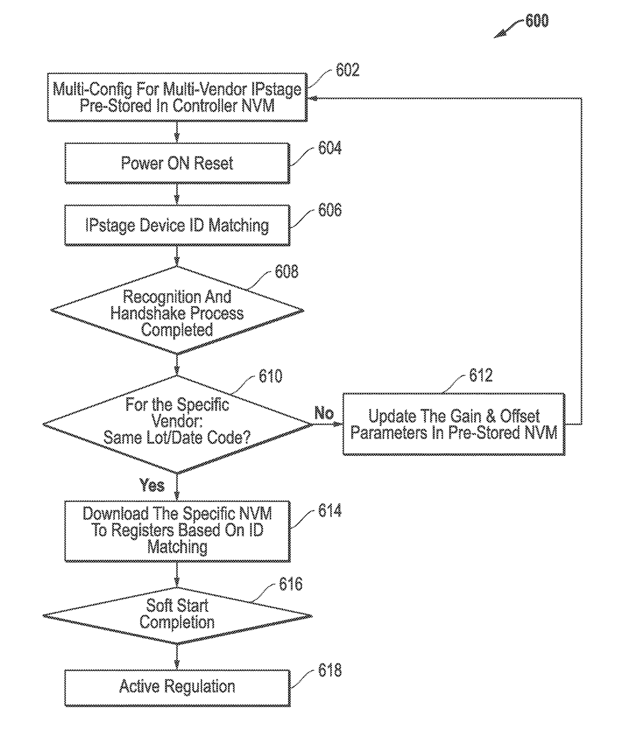
The patent text describes methods and systems for calibrating a multi-phase voltage regulator (VR) system during the development phase to ensure accuracy and avoid the need for production calibration. The disclosed systems and methods can use different types of IPstages with different electrical characteristics and current sense accuracy in a common VR system configuration, reducing concerns about continuity of supply. The VR controller can automatically select an optimized IPstage configuration file that matches a particular type of IPstage or perform a second stage fine calibration based on the smart IPstage. The methods and systems can improve accuracy, power saving, and reliability of the VR system and allow for different types of IPstages to be employed with different types of VR controllers. The disclosed methods and systems can also reduce the cost and production time compared to performance during the production phase and achieve higher power density and efficiency. Overall, the patent text provides a solution for calibrating a multi-phase VR system during the development phase to achieve required accuracy and avoid the need for production calibration.

Problems solved by technology

Moreover, less printed circuit board (PCB) real estate is required for the disclosed development calibration since it saves space that would otherwise be required for loading / calibration test pads needed for production calibration, which may in turn jeopardize implementation of PCB layout optimization especially critical for space tight system applications such as blade severs.

Method used


Image

  • Methods and systems for calibration of voltage regulator systems with multiple types of power stages
  • Methods and systems for calibration of voltage regulator systems with multiple types of power stages
  • Methods and systems for calibration of voltage regulator systems with multiple types of power stages

Examples


Embodiment Construction

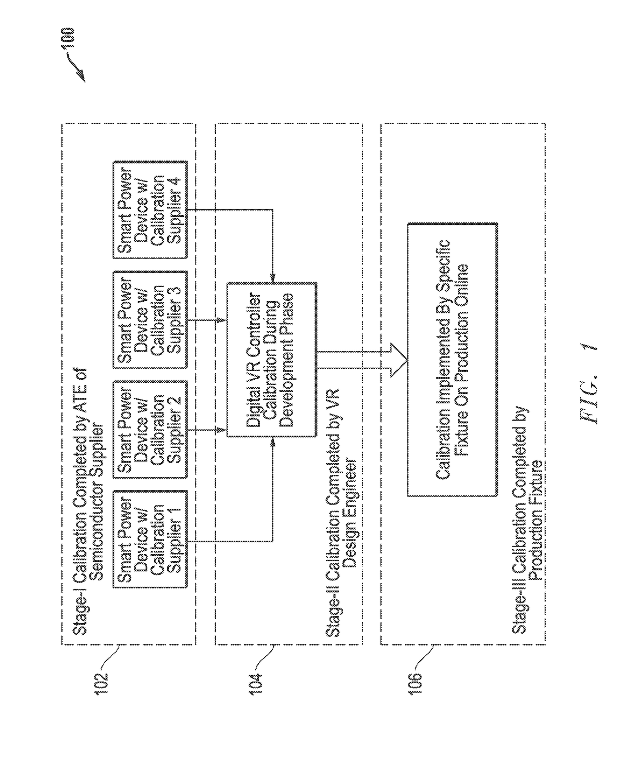
[0023]FIG. 1 illustrates relationship 100 between three stages of possible opportunities for implementing current sense calibration for a multi-phase VR system that range from IPstage fabrication stage calibration 102 to VR system design or development stage calibration 104 to VR system production stage calibration 106. The accuracy of current sense in a smart IPstage may be calibrated during stage (I) 102 by different manufacturer or supplier / vendor's automatic test equipment (ATE) process (e.g., to + / −4˜5% accuracy) in the heavy load range and even worse or less accuracy in light load range due to a weaker signal. This accuracy is below the + / −3% current sense accuracy currently required by CPU manufacturers. It will be understood that the degree of current sense accuracy may vary with system configuration, e.g., mirror FET current-sense technology may be implemented to achieve greater current sense accuracy than RDS (on) current sense. In any case, the accuracy of current sense m...


PUM


Abstract

Methods and systems are disclosed that may be employed to enable multi-phase voltage regulator (VR) system calibration during the development phase of a multi-phase VR system so as to meet defined accuracy targets and, in one example, to avoid the need for system level calibration in a production environment. The disclosed systems and methods may be further implemented to enable use of multiple sources for and types of integrated power stages (IPstages) in a common multi-phase VR system configuration while still achieving the required current sense accuracy, thus reducing or substantially eliminating continuity of supply (COS) concerns.

Description

[0001]This application claims the benefit of U.S. Provisional Patent Application Ser. No. 62 / 014,442, filed on Jun. 19, 2014 and entitled “Methods And Systems For Calibration Of Voltage Regulator Systems With Multiple Types Of Power Stages”, which is incorporated herein by reference in its entirety for all purposes.[0002]The present application is related in subject matter to concurrently filed patent application Ser. No. 14 / 470,344 entitled “METHODS AND SYSTEMS FOR IMPROVING LIGHT LOAD EFFICIENCY FOR POWER STAGES OF MULTI-PHASE VOLTAGE REGULATOR CIRCUITS” by Luo et al., and to concurrently filed patent application Ser. No. 14 / 470,455 entitled “METHODS AND SYSTEMS FOR IMPLEMENTING ADAPTIVE FET DRIVE VOLTAGE OPTIMIZATION FOR POWER STAGES OF MULTI-PHASE VOLTAGE REGULATOR CIRCUITS” by Luo et al. which is incorporated herein by reference in its entirety.FIELD OF THE INVENTION[0003]This application relates to information handling systems, and more particularly to power stage calibration ...

Claims


Application Information

Patent Timeline
Patent Type & Authority Patents(United States)
IPC IPC(8): G06F12/00G06F1/28G06F12/02
CPCG06F1/28G06F12/0238G06F12/0246Y02B60/1225Y02D10/00
Inventor LUO, SHIGUOZHANG, KEJIULI, HANGBREEN, JOHN J.
Owner DELL PROD LP
Learn More