Gear grinding unit

a technology of gear grinding and gear teeth, which is applied in the direction of gear teeth, manufacturing tools, manufacturing apparatus, etc., can solve the problems of increasing problematic incident equipment, requiring advanced working techniques, and the above-described threaded grindstone cannot be made with ease, so as to reduce the consumption of abrasives or the like, and the surface roughness is fine. , the effect of reducing the consumption of abrasives

Active Publication Date: 2017-05-23
NITOLEX CORP
View PDF20 Cites 0 Cited by
  • Summary
  • Abstract
  • Description
  • Claims
  • Application Information

AI Technical Summary

Benefits of technology

[0017]In the gear grinding unit of the first invention, the threaded grinding part is formed by overlapping the plurality of flexible abrasive sheets along the rotation axis with the bulge parts of the abrasive sheets mutually shifted around the rotation axis, so that when the threaded grinding part is pressed against the gear tooth, the abrasive sheets bend according to the profile of the tooth, thereby allowing the threaded grinding part to be in close contact with the tooth flank. Accordingly, the tooth flank can be ground uniformly and is not subjected to localized grinding. As a result, the tooth flank can be ground so as to have fine surface roughness. Moreover, the threaded grinding part does not require high-precision shaping so as to fit the profile of the gear tooth and can thus be made with ease.
[0018]Furthermore, the bending abrasive sheets exert their restoring force for returning to their respective original positions, so that the abrasive sheets are always pressed against the tooth flank. For this reason, even if the abrasive sheets wear away with use, the abrasive sheets can maintain their contact with the tooth flank, thereby eliminating the need for special shaping work such as dressing that a threaded grindstone requires.
[0019]In the gear grinding unit of the second aspect of the invention, the abrasive layer is provided only in the vicinity of the curved part on the surface of the backing of each of the abrasive sheets to be able to contact the tooth flank of the gear. Providing abrasive only to a part of each abrasive sheet that substantially comes into contact with the tooth flank allows the abrasive sheet to have a required grinding function and can reduce consumption of the abrasive or the like by a substantial amount.
[0020]Since the abrasive layer is not provided to a part other than in the vicinity of the curved part of the backing of the abrasive sheet, the abrasive sheet bends more flexibly than the abrasive sheet having the abrasive layer on the entire surface of the backing, thereby allowing the threaded grinding part to contact the tooth flank more closely. Thus, finer surface roughness can be obtained.
[0021]Moreover, centrifugal force associated with the rotational motion of the threaded grinding part can effectively act on the abrasive sheets, thereby causing the bending abrasive sheets to rise so as to return to their respective original positions. In this way, the abrasive sheets can be pressed against the tooth flank. Pressing force of the abrasive sheets with respect to the tooth flank can be adjusted by adjusting the centrifugal force, that is to say, adjusting rotational speed of the threaded grinding part.
[0022]In the gear grinding unit of the third aspect of the invention, the spacer is interposed between the adjacent abrasive sheets of the plurality of the abrasive sheets for providing the predetermined space, so that the degree of bending of the abrasive sheets can be adjusted with ease by adjusting spacer thickness, spacer diameter, the number of spacers and others.

Problems solved by technology

The above-described threaded grindstone, however, cannot be made with ease.
In order to grind the tooth flank of the gear to have fine surface roughness, the above-described threaded grindstone itself must be shaped with high accuracy to match a tooth profile of the gear, thus problematically requiring advanced working technique.
Thus, the incidental equipment problematically increases, and production efficiency problematically decreases.

Method used


Image

  • Gear grinding unit
  • Gear grinding unit
  • Gear grinding unit

Examples


first exemplary embodiment

Description of a Gear Grinding Device

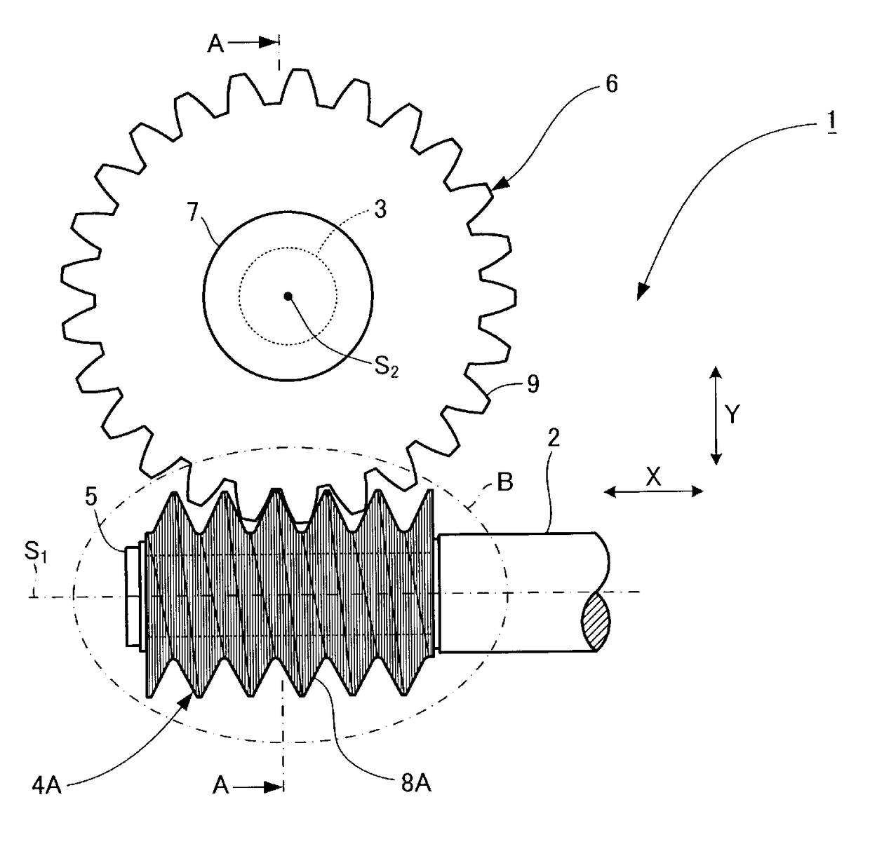
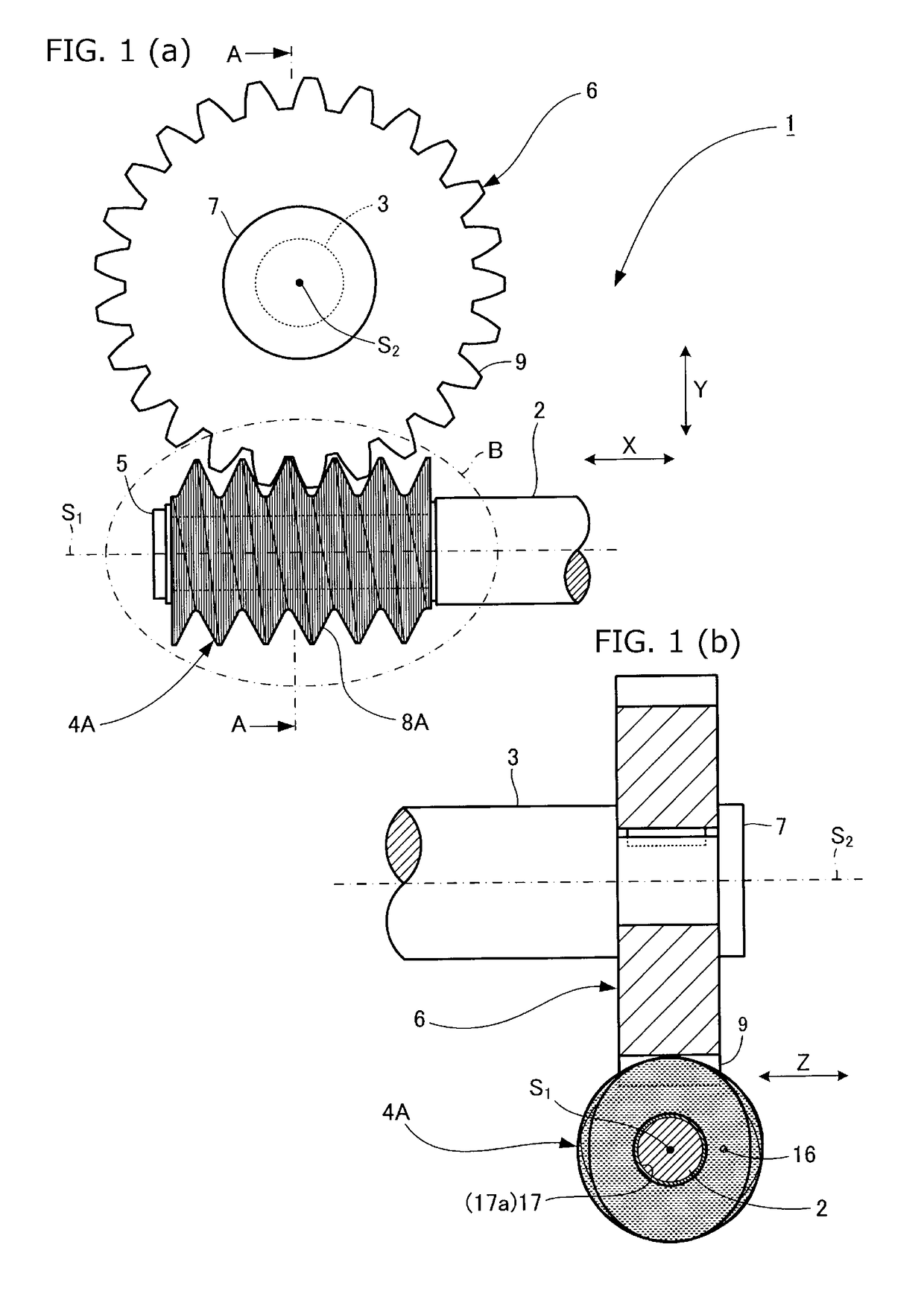
[0036]A gear grinding device 1 shown in FIGS. 1 (a) and 1 (b) is equipped with, in a three-axis control system formed of an X axis, a Y axis and a Z axis which are orthogonal to one another, a main spindle 2 rotatively driven around a rotation axis S1 extending along the X axis, and a table shaft 3 rotatively driven around a rotation axis S2. The rotation axis S2 is positioned at a predetermined distance from the rotation axis S1 along the Y axis orthogonal to the X axis to be perpendicular to the rotation axis S1 and extends along the Z axis.

[0037]The main spindle 2 is movable along the X, Y and Z axes.

[0038]The main spindle 2 is mounted with a detachable worm-shaped gear grinding unit 4A. It is to be noted that reference mark 5 denotes a fastener for holding the gear grinding unit 4A firmly on the main spindle 2.

[0039]As the main spindle 2 is rotatively driven, the gear grinding unit 4A rotates around the rotation axis S1 together with the main...

second exemplary embodiment

[0072]FIG. 8 (a), FIG. 8 (b) and FIG. 8 (c) illustrate an abrasive sheet of a gear grinding unit in accordance with the second exemplary embodiment of the present invention, with FIGS. 8 (a) to 8 (c) being a front view, a side view and a rear view of the abrasive sheet, respectively. FIG. 9 (a) is an enlarged view of an essential part showing the gear grinding unit of the second embodiment and a gear in an engaging condition, and FIG. 9 (b) is an enlarged view of part F in FIG. 9 (a).

[0073]It is to be noted that in the second embodiment, elements which are the same as or similar to those in the first embodiment have the same reference marks in the drawings, and the detailed descriptions of those elements are omitted. Emphasis is placed hereinafter on distinctive characteristic of the second embodiment, (and the same goes for a third exemplary embodiment which will be described later).

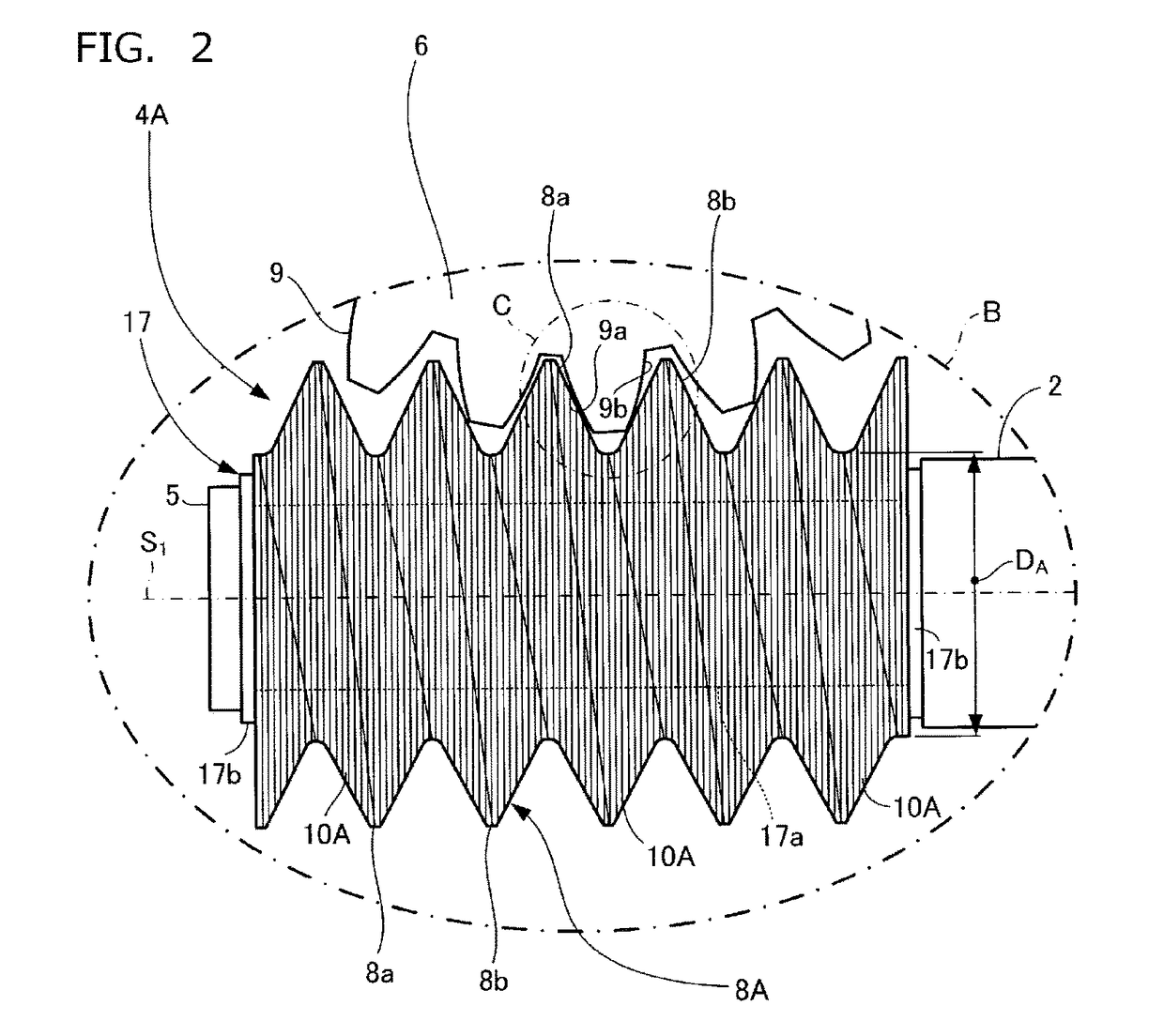
[0074]The abrasive sheet 10A of the first embodiment has, as shown in FIGS. 4 (a) to 4 (c), the abra...

third exemplary embodiment

[0078]FIG. 10 is an enlarged view of an essential part showing a gear grinding unit of the third exemplary embodiment and a gear in an engaging condition.

[0079]In the gear grinding unit 4A of the first embodiment, the plurality of the abrasive sheets 10A are arranged close to one another as shown in FIG. 6 (a) and FIG. 6 (b), whereas in a plurality of the abrasive sheets 10A of a gear grinding unit 4C of the third embodiment, a spacer 23 is interposed between the adjacent abrasive sheets 10A for providing a predetermined space, and with the spacers 23 interposed, the plurality of the abrasive sheets 10A are overlapped along the rotation axis S1, thus forming a threaded grinding part 8C.

[0080]It goes without saying that the gear grinding unit 4C of the third embodiment can obtain the same effects as the gear grinding unit 4A of the first embodiment. Moreover, the spacer 23 interposed between the adjacent abrasive sheets 10A of the plurality of the abrasive sheets 10A provides the pre...


PUM


Abstract

A gear grinding unit, capable of grinding a tooth flank of a gear to have fine surface roughness without requiring any special shaping work such as dressing, includes a threaded grinding part which is rotatable around a rotation axis (S1) and engages with a tooth of a gear to be ground. Through a rotational motion of the threaded grinding part, a tooth flank of the gear is ground. The threaded grinding part includes a plurality of flexible abrasive sheets each including a virtual circle having a diameter that equals a root diameter (DA) of the threaded grinding part and a bulge part bulging radially outward from the virtual circle. With the bulge parts of the abrasive sheets mutually shifted around the rotation axis (S1), the abrasive sheets are overlapped along the rotation axis (S1) to form the threaded grinding part.

Description

TECHNICAL FIELD[0001]The present invention relates to a gear grinding unit which grinds a tooth flank of a gear by bringing a threaded grinding function part into contact with a gear tooth.BACKGROUND ART[0002]Recently, in the field of automobiles that places importance on comfortability and fuel efficiency, fine surface roughness of a gear used for a transmission or the like to achieve less noise, less vibration and lower fuel consumption has been increasingly demanded.[0003]To achieve fine surface roughness of a gear, a conventional technique is such that the gear and a threaded grindstone are mutually rotated in engaging relation for generation grinding of a tooth flank of the gear (refer to, for example, Patent Document 1).RELATED ART DOCUMENTPatent Document[0004]Patent Document 1: Japanese Patent Unexamined Publication No. 2013-018117[0005]As an example of the threaded grindstone mentioned above, there has been proposed a grindstone which has a threaded grinding surface formed o...

Claims


Application Information

Patent Timeline
Patent Type & Authority Patents(United States)
IPC IPC(8): B23F21/02B24D13/02
CPCB23F21/026B23F21/02B24D13/02
Inventor NURIYA, TAKAHIKOMORIOKA, SHOICHI
Owner NITOLEX CORP
Why Eureka
Try Eureka