
Pipe insulation fitting cover

a technology of fitting cover and fitting, which is applied in the direction of seals, identification means, instruments, etc., can solve the problems of pipe system itself failing, undesired energy loss, and pipe fitting cover of the type mentioned above being formed from a pair of semis, so as to prevent moisture infiltration, facilitate and protect moisture infiltration, and improve the effect of protection

Inactive Publication Date: 2017-05-09
CHILLED WATER FITTINGS INC
View PDF4 Cites 0 Cited by
  • Summary
  • Abstract
  • Description
  • Claims
  • Application Information

AI Technical Summary

Benefits of technology

[0010]It is therefore an object of the present invention to provide a single integral structure pipe cover for covering an angled joint such as an elbow joint, tee joint, etc. which provides greater protection against moisture infiltration and is easier and significantly less expensive to install on below ambient temperature pipe systems than known pipe covers. It is another object of the invention to provide a single integral structure pipe cover wherein the peripheral edges thereof have integrated gaskets to thereby prevent moisture infiltration.

Problems solved by technology

The difficulty is that pipe fitting covers of the type mentioned above being formed from a pair of semi-circular sections are disadvantageous because they have seams which may split or crack and thereby eventually leak.
Unless the pipe insulation, especially at an angled pipe joint is tightly sealed, the pipe insulation customarily used around the pipe can fail due to moisture intrusion, causing undesired energy loss.
The pipe system itself may also fail due to corrosion arising from the infiltration of moisture and resultant condensation under the jacketing surrounding the insulation.
These methods, however, have had limited success.
Adhesives are disadvantageous because the opposed ends tend to separate from each other especially when the adhesive cracks due to the often severe temperature and humidity conditions in vicinity of the pipe joint.
Further, where these covers overlap onto the adjacent straight sections of insulation, the application of a coating to seal the joint at these locations necessitates significant manual labor.
Often the coating still can't be applied continuously around the pipe cover because of its remote location.

Method used


Image

  • Pipe insulation fitting cover
  • Pipe insulation fitting cover
  • Pipe insulation fitting cover

Examples


Embodiment Construction

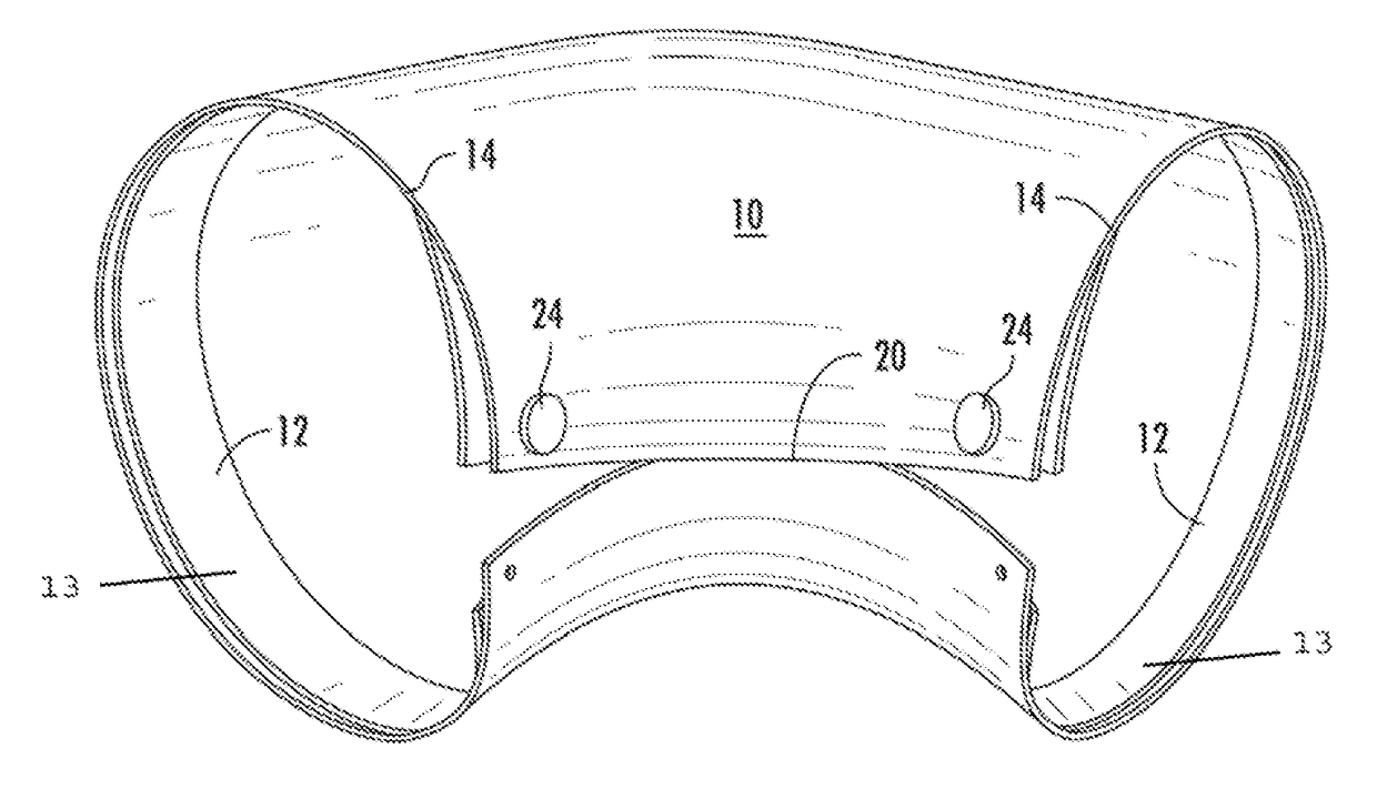
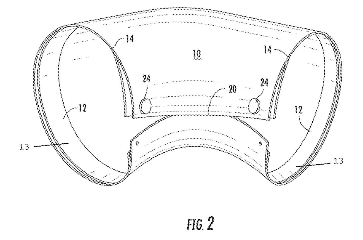
[0018]Now referring to the drawings, an embodiment of the insulation shell fitting of the present invention is shown and generally illustrated in the figures. As can be seen, the insulation shell fitting 10 generally includes a shell body that is configured to encompass the piping joint and the adjacent insulation, and a gasket 12 that serves to seal the shell fitting against moisture infiltration when the shell fitting is in its installed position.

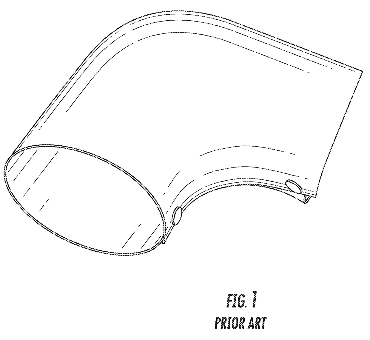
[0019]As stated above, the present invention disclosed a shell type fitting cover similar in structure to those fittings that are conventional in the prior art and shown at FIG. 1. In the scope of the present invention as illustrated at FIG. 2, the body of the shell fitting 10 is preferably formed using a polymer material or a flexible thermoplastic sheet. The body of the shell fitting 10 is shaped such a manner that when positioned over the pipe joint, the fitting conforms to the shape and angle of the pipe joint. As can be seen viewing ...


PUM


Abstract

A shell type fitting cover provided and is formed from a polymer material or a flexible thermoplastic sheet. A continuous gasket is affixed to the peripheral edges of the shell fitting prior to its installation. Preferably the gasket is a flexible, compressible material. The fitting includes a shell having two ends that overlap onto the linear portions of a pipe insulation system and a longitudinal seam that allows the shell to be installed over an existing piping system. A strip of foam gasket material is provided along each of the peripheral edges in order to create a seal where the installed fitting overlaps the linear sections of insulation as well as where the fitting shell overlaps itself at the longitudinal joint.

Description

CROSS-REFERENCE TO RELATED APPLICATIONS[0001]This application is related to and claims priority from earlier filed U.S. Provisional Patent Application No. 61 / 551,503, filed Oct. 26, 2011.BACKGROUND OF THE INVENTION[0002]The present invention relates to a cover for use in connection with pipe insulation installed onto piping that operates at below ambient temperature. More specifically, the present invention relates to a fitting cover for use with a piping insulation system that includes integrated gasketing to insure an effective moisture resistant seal where the fitting meets the straight sections of insulation.[0003]Pipe fitting covers for angled joints such as elbow joints, tee joints, etc. are already known in the art. There are a number of split jacket housing systems for pipe elbows having sections with overlapping connecting flanges and interengageable ribs and grooves. The difficulty is that pipe fitting covers of the type mentioned above being formed from a pair of semi-cir...

Claims


Application Information

Patent Timeline
Patent Type & Authority Patents(United States)
IPC IPC(8): G09F3/00F16L25/00F16L59/11F16L59/22
CPCF16L25/00F16L59/11F16L59/22
Inventor PURDON, JEFFREY
Owner CHILLED WATER FITTINGS INC
Learn More