
System and method for welding tubular workpieces

Active Publication Date: 2017-05-09
FUSERING INC
View PDF17 Cites 17 Cited by
  • Summary
  • Abstract
  • Description
  • Claims
  • Application Information

AI Technical Summary

Benefits of technology

The invention provides a system and method for joining metal workpieces together using an intermediate clamp, induction coils, and workpiece clamps. The system and method allow for the secure engagement of the intermediate clamp, the heating of the open ends of the workpieces in a non-oxidizing atmosphere to provide hot portions, the heating of the intermediate workpiece to provide hot intermediate portions, and the positioning of the workpieces to cause plastic deformation in at least part of the hot portions to bond them together. The technical effects of the invention include improved bonding efficiency, reduced oxidation damage, and improved process control.

Problems solved by technology

However, in certain circumstances (e.g., where long segments of pipe are to be joined together, for instance, when laying a pipeline), rotation of one or both of the workpieces is not feasible.

Method used


Image

  • System and method for welding tubular workpieces
  • System and method for welding tubular workpieces
  • System and method for welding tubular workpieces

Examples


Embodiment Construction

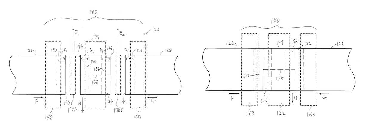
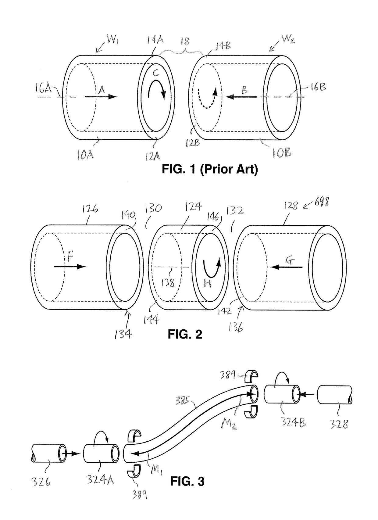
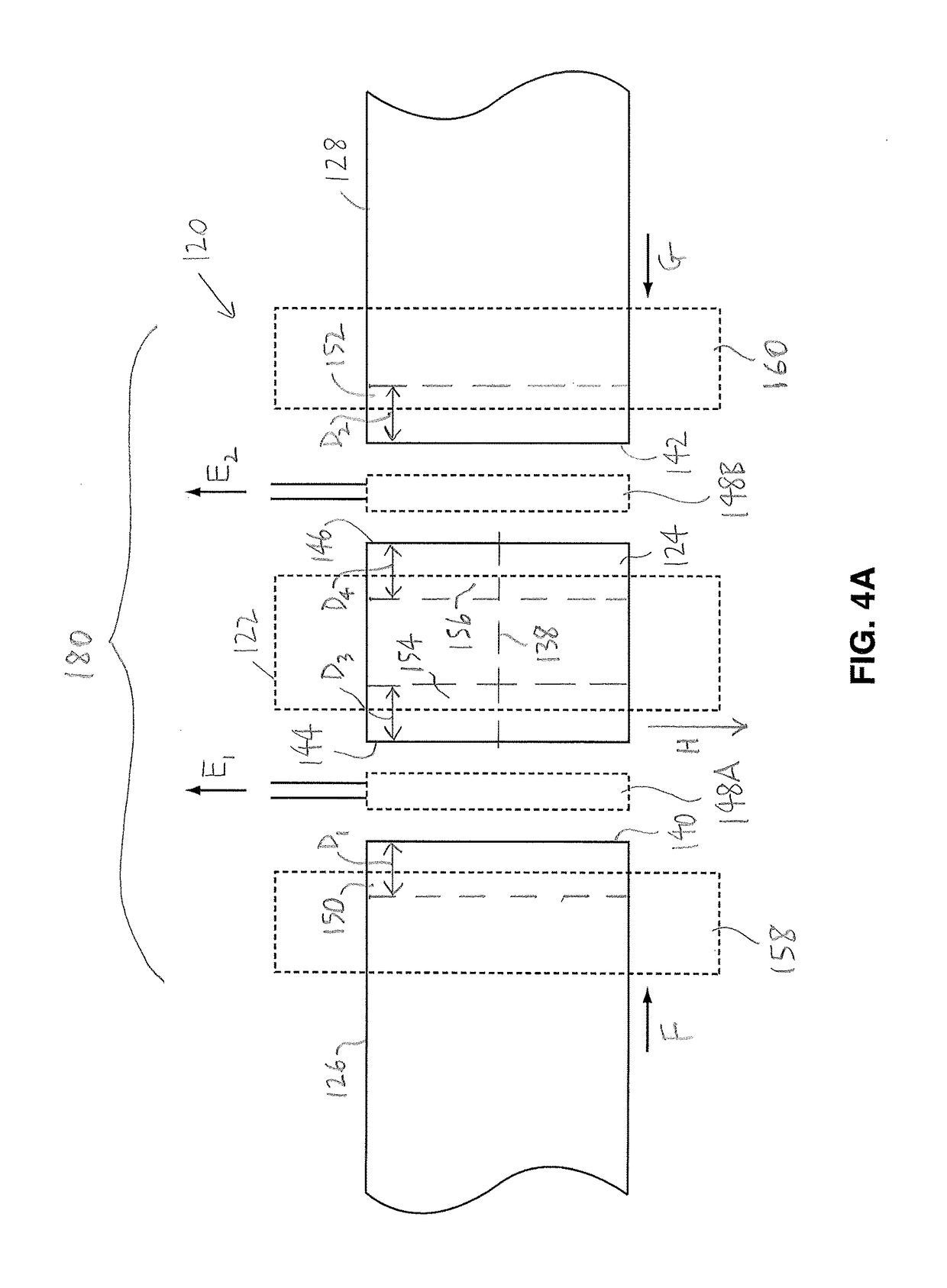
[0042]In the attached drawings, like reference numerals designate corresponding elements throughout. Reference is first made to FIGS. 2-6B and 8 to describe an embodiment of a system of the invention referred to generally by the numeral 120. As will be described, the system 120 is for joining metal workpieces together. In one embodiment, the system 120 preferably includes an intermediate clamp 122, for securely engaging an intermediate tubular workpiece 124 positioned between two workpieces 126, 128 to define respective gaps 130, 132 between tubular open ends 134, 136 thereof, and for at least partially rotating the intermediate workpiece 122 about an axis 138 thereof, as will be described. As can be seen in FIGS. 2 and 4A, each of the two workpieces 126, 128 preferably has one or more contact surfaces 140, 142 at the open ends 134, 136 thereof facing respective intermediate contact surfaces 144, 146 of the intermediate tubular workpiece 122. It is also preferred that the system 120...


PUM

PropertyMeasurementUnit
Temperatureaaaaaaaaaa
Thicknessaaaaaaaaaa
Angleaaaaaaaaaa

Abstract

A method of joining metal workpieces together. The method includes an intermediate metal workpiece between first and second metal workpieces to define gaps therebetween, and positioning induction coils in the gaps. The induction coils are energized, to heat hot portions in the first and second workpieces and intermediate hot portions in the intermediate workpiece in a non-oxidizing atmosphere to at least a hot working temperature. The induction coils are removed from the gaps, and the intermediate workpiece is rotated about an axis thereof. Contact surfaces on the first and second workpieces are pressed against the intermediate contact surfaces of the intermediate workpiece respectively while the intermediate workpiece is rotating, for plastic deformation of at least part of the metal in the hot portions and in the hot intermediate portions. The first, second, and intermediate workpieces are cooled to bond the first and second metal workpieces and the intermediate workpiece together.

Description

[0001]This application claims priority from U.S. Provisional Patent Application No. 61 / 803,596, filed on Mar. 20, 2013, the entire disclosure whereof is hereby incorporated by reference herein.FIELD OF THE INVENTION[0002]The present invention is a system and a method for joining metal workpieces together.BACKGROUND OF THE INVENTION[0003]As is known in the art, metal parts having opposed substantially planar and parallel surfaces may be welded together by a process described as solid state welding. A method of solid state welding is disclosed by U.S. Pat. No. 6,637,642 (Lingnau).[0004]As an example, a conventional method of solid state welding two tubular workpieces together is illustrated in FIG. 1. (As will be described, the balance of the drawings illustrate the present invention.) Two metal workpieces to be welded together using the solid state welding method of the prior art are identified in FIG. 1 as “W1” and “W2”. Typically, the workpieces “W1” and “W2” include open ends havi...

Claims


Application Information

Patent Timeline
IPC IPC(8): B23K13/01F16L9/02B23K31/02
CPCF16L9/02B23K31/02F16L13/02B23K13/015B23K20/12B23K28/02B23K2101/06
Inventor CHENG, PAUL PO
Owner FUSERING INC
Learn More