
Electrophotographic member, process cartridge, and electrophotographic apparatus

a technology of electrophotography and process cartridges, applied in the direction of electrographic process apparatus, instruments, corona discharge, etc., can solve the problems of reducing the quality of electrophotographic images, unable to readily prevent the generation of local low resistance portions, and difficult homogeneous dispersal of electro-conductive particles such as carbon black, so as to achieve high-quality electrophotographic images and reduce the bleeding out of an ion conducting agent.

Active Publication Date: 2017-05-02
CANON KK
View PDF10 Cites 39 Cited by
  • Summary
  • Abstract
  • Description
  • Claims
  • Application Information

AI Technical Summary

Benefits of technology

This patent describes how certain chemicals in a resin can affect the electrical conductivity of a layer. The patent explains that certain chemicals have a positive charge on a nitrogen atom, which reduces the interaction between the chemical and other atoms in the resin. This allows the chemical to move around and increase the electrical conductivity of the layer. The patent also explains that certain other chemicals can bond to the positive charge on the nitrogen atom, creating steric hindrance that prevents the chemical from approaching the positive charge. This results in reduced electrical conductivity. Overall, the patent discusses how certain chemicals can affect the electrical conductivity of a resin layer and how to optimize the electrical performance of the resin layer for various applications.

Problems solved by technology

On the other hand, the electro-conductive particles such as carbon black are difficult to homogeneously disperse, and generation of portions locally having low resistance is not readily prevented.
However, the fixation of the ion conducting agent might reduce the electro-conductivity of the electro-conductive layer, so that the electro-conductivity required for the electrophotographic member was not attained, thus degrading the quality of electrophotographic images.

Method used

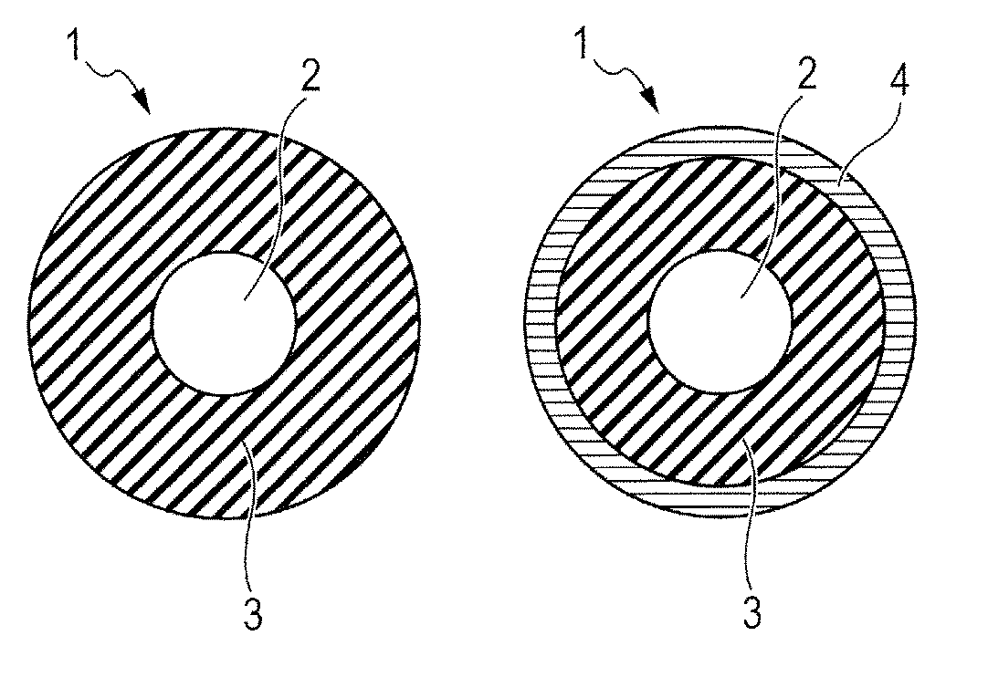
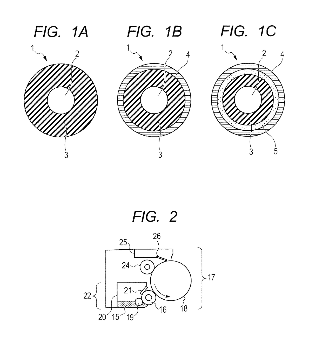
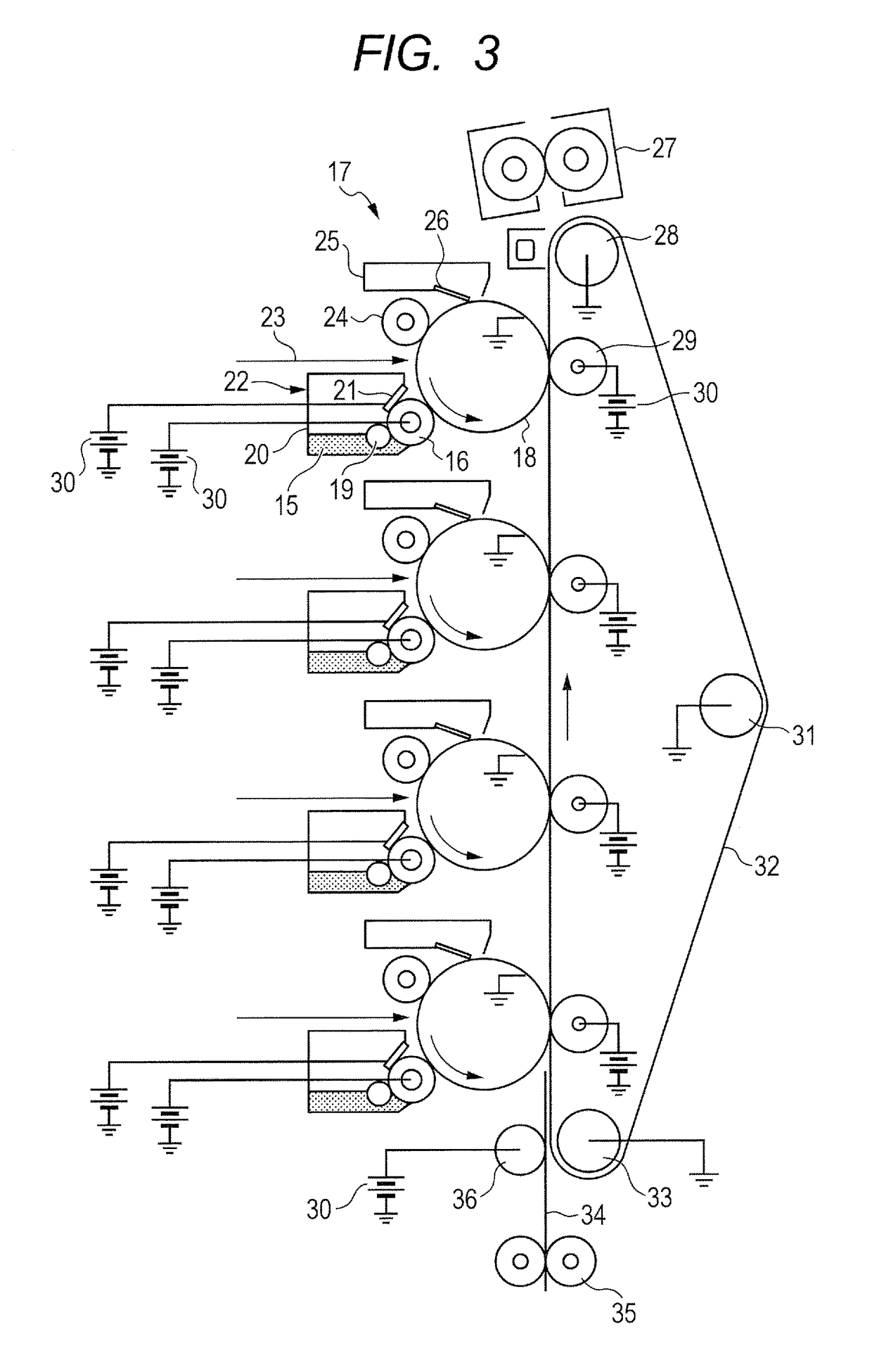

Image

  • Electrophotographic member, process cartridge, and electrophotographic apparatus
  • Electrophotographic member, process cartridge, and electrophotographic apparatus
  • Electrophotographic member, process cartridge, and electrophotographic apparatus

Examples


example 1

[0178]The method of producing the electrophotographic member according to the present invention will now be described.

[0179]The following materials were mixed by stirring to prepare a material for a surface layer.[0180]reactive compound[0181]Isocyanate group-terminated prepolymer B-1 66.4 parts by mass[0182]polyol[0183]Polyol E-1 (poly(tetramethylene glycol) (available from Mitsubishi Chemical Corporation)) 30.6 parts by mass[0184]ion conducting agent[0185]Ion conducting agent C-1 3.0 parts by mass[0186]urethane resin fine particles (trade name, Art-pearl C-400; available from Negami Chemical Industrial Co., Ltd.) 90.0 parts by mass

[0187]Next, methyl ethyl ketone (hereinafter, referred to as MEK) was added to the mixture such that the total solid content was 30% by mass, and was mixed with a sand mill. The viscosity of the mixture was adjusted with MEK to 10 to 13 cps to prepare a coating material for forming a surface layer.

[0188]Elastic roller D-1 prepared above was immersed in th...

example 8

[0206]A method of producing another electrophotographic member according to the present invention will now be described.

[0207]The following materials were mixed by stirring to prepare a material for a surface layer.[0208]reactive compound[0209]Reactive compound R-2 (bisphenol A diglycidyl ether (available from Tokyo Chemical Industry Co., Ltd.)) 18.0 parts by mass[0210]polyol[0211]Polyol E-4 (polyethylene glycol (available from Sanyo Chemical Industries, Ltd.)) 72.0 parts by mass[0212]ion conducting agent[0213]Ion conducting agent C-8 10.0 parts by mass[0214]urethane resin fine particles (trade name, Art-pearl C-400; available from Negami Chemical Industrial Co., Ltd.) 90.0 parts by mass

[0215]Next, methyl ethyl ketone (hereinafter, referred to as MEK) was added to the mixture such that the total solid content was 30% by mass, and was mixed with a sand mill. The viscosity of the mixture was adjusted with MEK to 10 to 13 cps to prepare a coating material for forming a surface layer.

[0...

example 9

[0217]A method of producing another electrophotographic member according to the present invention will now be described.

[0218]The following materials were mixed by stirring to prepare a material for a surface layer.[0219]reactive compound[0220]Reactive compound R-3 (2,4,6-tris[bis(methoxy methyl)amino]-1,3,5-triazine (available from Tokyo Chemical Industry Co., Ltd.)) 15.0 parts by mass[0221]polyol[0222]Polyol E-4 (polyethylene glycol (available from Sanyo Chemical Industries, Ltd.)) 82.0 parts by mass[0223]ion conducting agent[0224]Ion conducting agent C-9 3.0 parts by mass[0225]urethane resin fine particles (trade name, Art-pearl C-400; available from Negami Chemical Industrial Co., Ltd.) 90.0 parts by mass

[0226]Next, methyl ethyl ketone (hereinafter, referred to as MEK) was added to the mixture such that the total solid content was 30% by mass, and was mixed with a sand mill. The viscosity of the mixture was adjusted with MEK to 10 to 13 cps to prepare a coating material for form...


PUM


Abstract

The present invention provides a highly electro-conductive electrophotographic member which contributes to formation of high-quality electrophotographic images while bleeding out of an ion conducting agent is reduced, a process cartridge, and an electrophotographic apparatus. Accordingly, the electrophotographic member according to the present invention includes an electro-conductive mandrel and an electro-conductive layer, wherein the electro-conductive layer contains a resin synthesized from a nitrogen-containing aromatic heterocyclic cation and a compound being able to react with the nitrogen-containing aromatic heterocyclic cation, and an anion; the nitrogen-containing aromatic heterocyclic cation has two substituents bonded to hydroxyl groups; and the substituent bonded to the hydroxyl group is bonded to a nitrogen atom of a nitrogen-containing aromatic heterocycle of the nitrogen-containing aromatic heterocyclic cation.

Description

BACKGROUND OF THE INVENTION[0001]Field of the Invention[0002]The present invention relates to an electrophotographic member included in an electrophotographic apparatus, and a process cartridge and an electrophotographic apparatus including the electrophotographic member.[0003]Description of the Related Art[0004]In electrophotographic apparatuses (electrophotographic copiers, fax machines, printers and the like of an electrophotographic type), an electrophotographic photosensitive member (hereinafter also referred to as “photosensitive member”) is charged by a charging roller, and is exposed to laser beams and the like to form an electrostatic latent image on the photosensitive member. A toner in a developing container is then applied onto a developing roller with a toner feed roller and a toner control member. Next, the toner is conveyed to a region to be developed with the developing roller. The electrostatic latent image on the photosensitive member is developed in or around the ...

Claims


Application Information

Patent Timeline
Patent Type & Authority Patents(United States)
IPC IPC(8): G03G15/02G03G15/08G03G5/043
CPCG03G5/043G03G15/0233G03G15/0818
Inventor YAMAGUCHI, SOSUKEYAMADA, MASAKIARIMURA, HIDEYAYAMAUCHI, KAZUHIRONISHIOKA, SATORU
Owner CANON KK
Learn More