
Dual-lobed cam for a camshaft and engine assembly

a camshaft and engine technology, applied in the direction of valve details, valve arrangements, valve drives, etc., can solve the problems that many of these technological advancements do not operate to reduce the torque or energy required to turn the camshaft and thus operate the engine, so as to reduce the torque or power required to rotate the camshaft, reduce and reduce the effect of the rotational speed of the camsha

Active Publication Date: 2017-05-02
PLOUGHE KEVIN
View PDF4 Cites 0 Cited by
  • Summary
  • Abstract
  • Description
  • Claims
  • Application Information

AI Technical Summary

Benefits of technology

The present invention is about a special cam design for an internal combustion engine that reduces the speed of the camshaft. This invention uses dual-lobed cams that make it possible for a single cam to engage with a valve assembly twice for every swing of the camshaft. This slows down the camshaft, which in turn reduces the torque or power needed to rotate it. As a result, the engine is more efficient and powerful.

Problems solved by technology

However, many of these technological advancements do not operate to reduce the torque or energy that is required to turn the camshaft and thereby operate the engine.

Method used


Image

  • Dual-lobed cam for a camshaft and engine assembly
  • Dual-lobed cam for a camshaft and engine assembly
  • Dual-lobed cam for a camshaft and engine assembly

Examples


Embodiment Construction

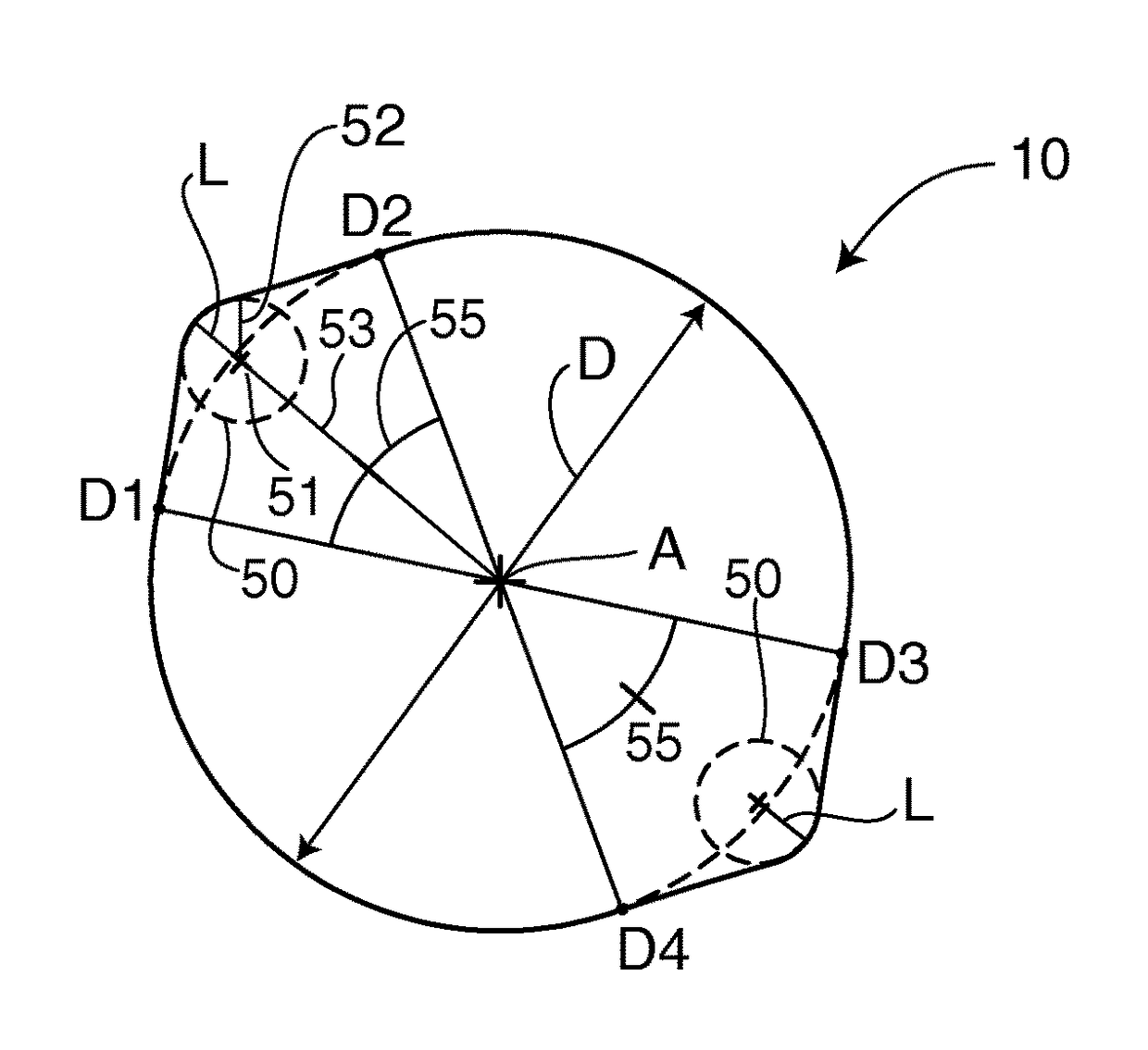
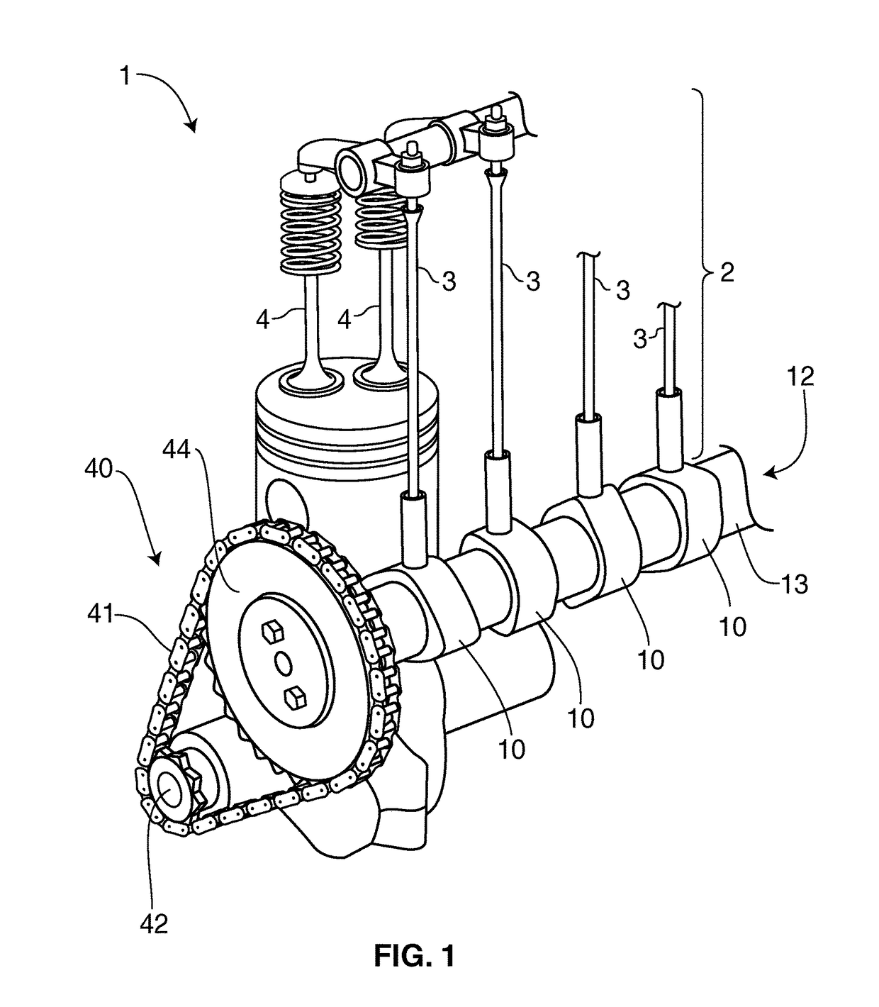
[0025]As shown in the accompanying drawings, the present invention is directed to a new and improved dual-lobed cam, generally referenced as 10, for a camshaft 12 of an internal combustion engine 1. As provided herein, certain embodiments further include a timing assembly 40, such as a crankshaft sprocket, camshaft sprocket and one or more timing belts, timing chains, etc.

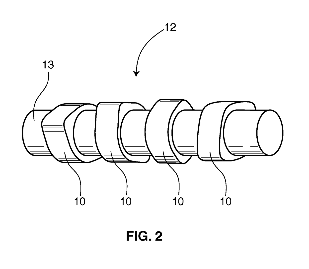
[0026]For example, in use, a plurality of the dual-lobed cams 10 of the present invention will generally be disposed in a spaced relation to one another along the length of a camshaft 12 (FIG. 2) for interactive disposition or driving relation with a valve assembly 2, which may include, depending on the particular engine 1, one or more valves, lifters, push rods, rocker shaft(s), valve spring(s), etc. Particularly, in the illustrative set-up or embodiment shown in FIG. 1, the dual lobed cams 10 of the camshaft 12 are disposed in a driving relation with corresponding push rods 3, which in turn manipulate the corresp...


PUM


Abstract

A dual-lobed cam for a camshaft of an internal combustion engine is presented herein. The camshaft includes an elongated shaft rotationally disposed in relation to a crankshaft via a timing assembly. The dual-lobed cam includes an enlarged base circle region circumferentially disposed around the camshaft, with two oppositely disposed lobes extending therefrom. The lobes define lift regions off of the base circle which drivingly engage a valve assembly. The camshaft disclosed herein may include a rotational speed of one-fourth the rotational speed of a crankshaft or crankshaft sprocket, thereby preserving power and increasing efficiency of the overall engine.

Description

CLAIM OF PRIORITY / CROSS REFERENCE TO RELATED APPLICATION[0001]The present application is based on and a claim to priority is made under 35 U.S.C. §119(e) to provisional patent application Ser. No. 61 / 842,963, having a filing date of Jul. 3, 2013, the contents of which are incorporated herein their entirety.FIELD OF THE INVENTION[0002]The present invention is generally directed to a dual-lobed cam for a camshaft of an internal combustion engine, the dual-lobed cam having a two lobes disposed on opposite sides of the cam base circle, or one hundred and eighty degrees apart from one another. In this manner, the rotational speed of the dual-lobed cam will be significantly lower (e.g., half) that of a conventional cam, and one fourth that of the crankshaft.BACKGROUND OF THE INVENTION[0003]Engine efficiency and power is a growing concern and has been the subject of various technological advancements in the automotive industry for many years. However, many of these technological advancemen...

Claims


Application Information

Patent Timeline
IPC IPC(8): F01L1/04F01L1/34
CPCF01L1/34F01L2001/054F01L1/022F01L1/047F01L1/08F01L2250/02F01L2250/04F01L2820/01
Inventor PLOUGHE, KEVIN
Owner PLOUGHE KEVIN
Learn More