Method and mould arrangement for explosion forming
a technology of explosive forming and mould arrangement, which is applied in the field of method and tool arrangement for explosive forming, can solve the problems of expensive methods and time-consuming, and achieve the effect of method and tool arrangement, suitable for mass production
- Summary
- Abstract
- Description
- Claims
- Application Information
AI Technical Summary
Benefits of technology
Problems solved by technology
Method used
Image
Examples
first embodiment
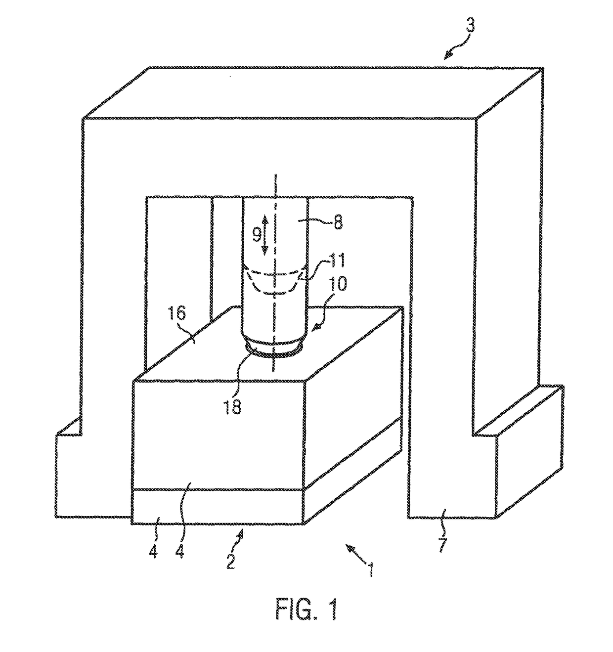
[0034]FIG. 1 shows a perspective view of a tool arrangement 1 according to the invention in accordance with the invention. The tool arrangement 1 in this embodiment comprises a moulding tool 2 and an ignition aggregate 3.
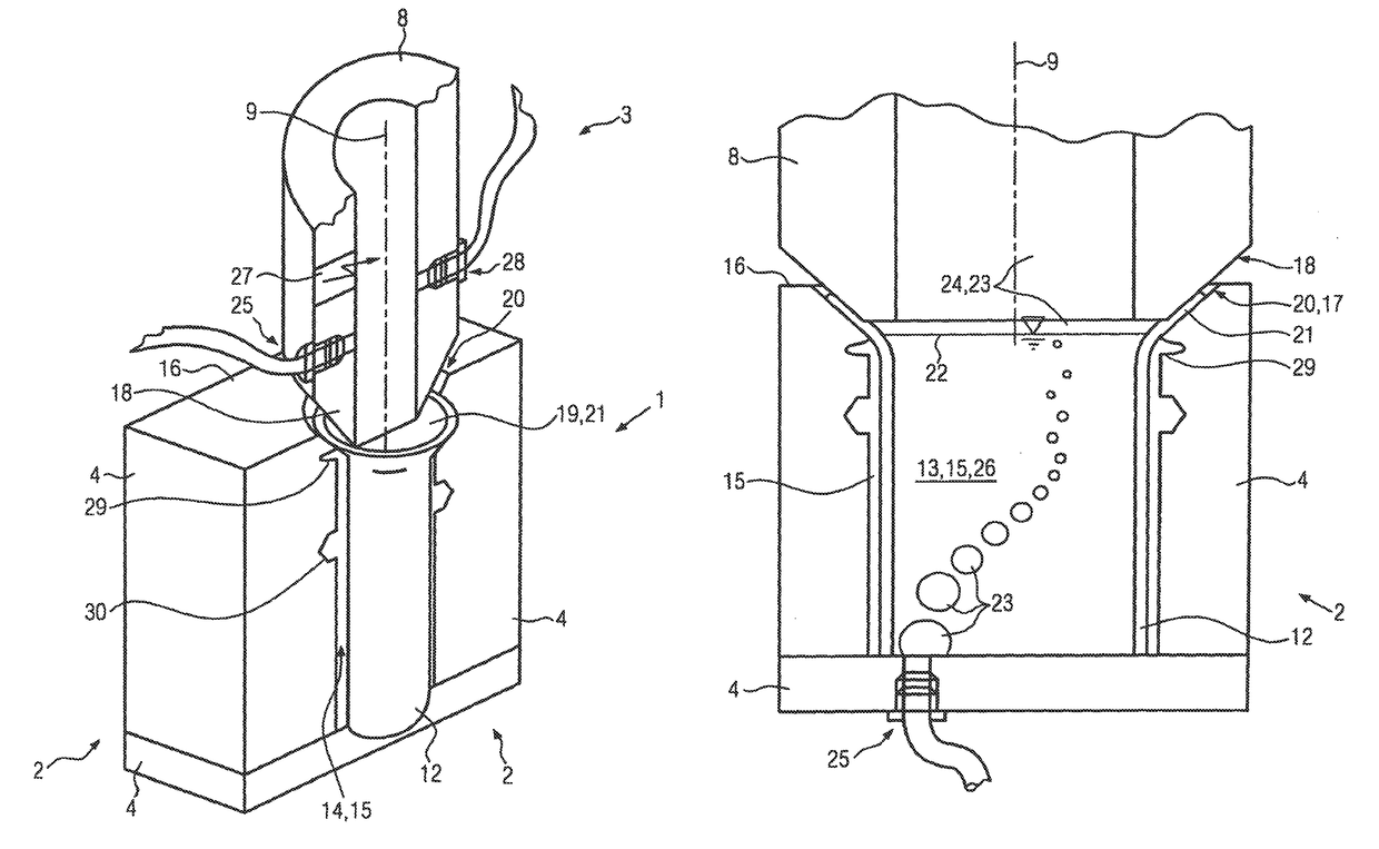
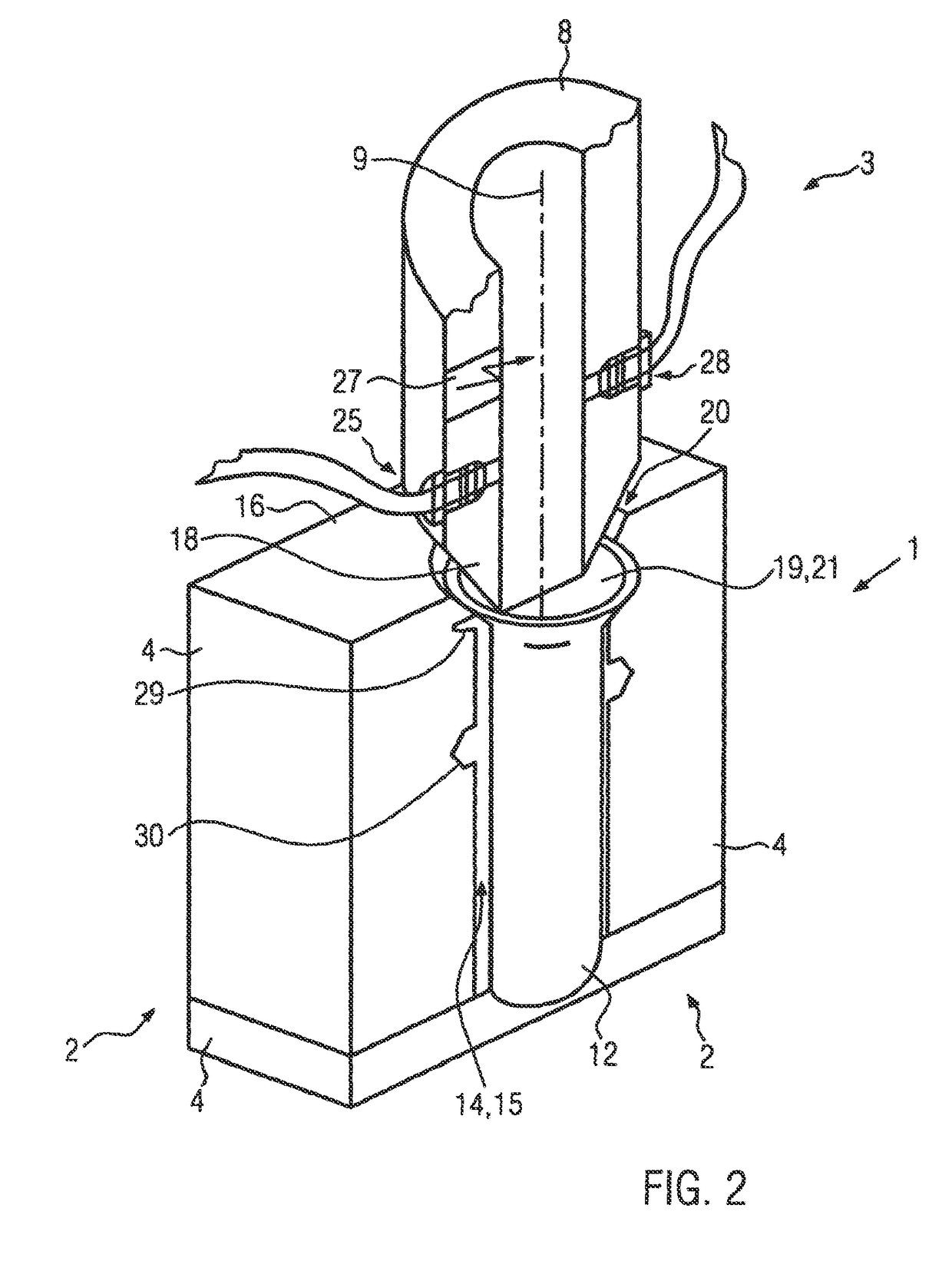
[0035]The moulding tool 2 is formed in a multiple number of pieces. It consists of a multiple number of mould halves 4, which can be assembled into the moulding tool 2. When closed, which means when all mould tool halves 4 are assembled together, a mould cavity 14 results in the interior of the moulding tool 2, whereby the contour of this mould cavity 14 produces the later shape of the completed workpiece. In addition, cutting or separating edges 29 and matrices of holes 30 can be provided in the contour of the moulding tool 2, in order to simultaneously cut the workpiece during the explosive forming, as shown in FIGS. 3 to 5. The mould cavity 14 simultaneously forms an intake area 15 of the moulding tool 2. According to the invention, the intake area 15 is at least...
second embodiment
[0047]FIG. 4 shows a cut through a tool arrangement 1 according to the invention in accordance with the invention. The reference numbers used in FIG. 4 indicate the same parts as in FIGS. 1 to 3, so that reference is made to the description for FIGS. 1 to 3 in this regard.
[0048]In FIG. 4, the intake area 15 or the workpiece cavity 13 is completely filled with the liquid. The explosive gas mixture 23 here is again located above the surface of the liquid 22. The gas connection 25 is located below the surface of the liquid 22 in this embodiment. It is arranged here in one of the moulding tool halves 4.
[0049]FIG. 5 shows a cut through the tool arrangement 1 according to the invention as shown in FIG. 4, but with a changed liquid level. The reference numbers used in FIG. 5 indicate the same parts as in FIGS. 1 to 4, so that reference is made to the description of FIGS. 1 to 4 in this regard.
[0050]The workpiece cavity 13 here is completely filled with liquid 26. The workpiece holding area...
PUM
| Property | Measurement | Unit |
|---|---|---|
| pressure | aaaaa | aaaaa |
| pressure | aaaaa | aaaaa |
| pressure | aaaaa | aaaaa |
Abstract
Description
Claims
Application Information
 - R&D
- Intellectual Property
- Life Sciences
- Materials
- Tech Scout
- Unparalleled Data Quality
- Higher Quality Content
- 60% Fewer Hallucinations
Browse by: Latest US Patents, China's latest patents, Technical Efficacy Thesaurus, Application Domain, Technology Topic, Popular Technical Reports.
© 2025 PatSnap. All rights reserved.Legal|Privacy policy|Modern Slavery Act Transparency Statement|Sitemap|About US| Contact US: help@patsnap.com


