Non-magnetic frequency selective limiters and signal-to-noise enhancers

a frequency selective limiter and signal-to-noise enhancer technology, applied in the direction of limiting amplitude, electrical equipment, waveguide devices, etc., can solve the problems of incompatibility with integrated circuit technology, bulky magnetic materials, heavy weight,

Active Publication Date: 2017-04-18
ROCKWELL COLLINS INC
View PDF5 Cites 0 Cited by
  • Summary
  • Abstract
  • Description
  • Claims
  • Application Information

AI Technical Summary

Benefits of technology

[0006]According to one embodiment, there is provided a non-magnetic material frequency selective limiter circuit that exhibits functionality of the magnetic frequency selective limiter. The circuit comprises: an input configured to receive an input signal; an output configured to output an output signal; a first resonator oscillating at a fundamental frequency to pass a signal having a frequency ω for an input signal having the frequency ω; a second resonator oscillating at one half of the fundamental frequency to pass a signal having a frequency ω / 2 for an input signal having the frequency ω; a non-linear coupling component non-linearly an parametrically coupling the first resonator and the second resonator, wherein the first resonator, second resonator and the non-linear coupling component are arranged so as to reduce the amplitude of an output signal for an input signal of frequency ω when an input signal amplitude is above a voltage threshold value, by converting part of the input signal to a signal at the frequency ω / 2, wherein the first resonator, second resonator and the non-linear coupling component are formed of non-magnetic materials.

Problems solved by technology

Magnetic material components, however, suffer from major drawbacks inherent to magnetic materials in general.
Such magnetic materials are bulky, heavy, incompatible with integrated circuit technologies, sensitive to temperature detuning, require permanent magnetic bias field, and are good only in a certain frequency range (due to fixed frequency of gyromagnetic precession).
Nonlinear magnetic materials are also extremely expensive since the quality requirements are higher than in the case of linear materials.

Method used


Image

  • Non-magnetic frequency selective limiters and signal-to-noise enhancers
  • Non-magnetic frequency selective limiters and signal-to-noise enhancers
  • Non-magnetic frequency selective limiters and signal-to-noise enhancers

Examples


Embodiment Construction

[0051]The present inventor has realized that the magnetostatic to spin-wave coupling of magnetic material FSLs can be mimicked in non-magnetic material based on parametrically coupled transmission line resonators. In this case, a non-magnetic material based FSL can be provided.

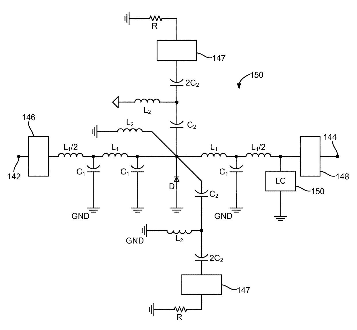
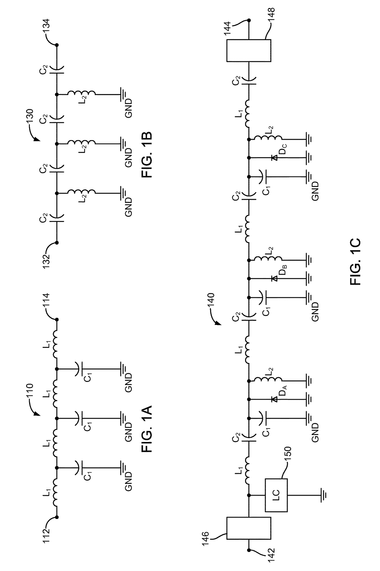
[0052]FIGS. 1A-1C illustrate a non-magnetic material FSL according to an embodiment, where FIG. 1A illustrates a first resonator oscillating at a fundamental frequency ωS, FIG. 1B illustrates a second resonator oscillating at one half the fundamental frequency ωS, i.e., at ωS / 2, and FIG. 1C and FIG. 1D illustrate the non-magnetic material FSL with the first resonator parametrically coupled with the second resonator.

[0053]Referring to FIG. 1A, the first resonator 110 oscillates at a fundamental frequency ωS. That is, for a signal with a frequency ω input to the first resonator 110, an output signal with a frequency ω is output. The first resonator 110 includes an input 112, which receives an input signal, and a...


PUM


Abstract

A non-magnetic material frequency selective limiter circuit has first and second resonators and a non-linear coupling component. The first resonator oscillates at a fundamental frequency. The second resonator oscillates at one half of the fundamental frequency. The non-linear coupling component non-linearly and parametrically couples the first resonator and the second resonator. The first resonator, second resonator and the non-linear coupling component are arranged so as to reduce the amplitude of an output signal for an input signal of frequency ω when an input signal amplitude is above a voltage threshold value, by converting part of the input signal to a signal at the frequency ω/2. The first resonator, second resonator and the non-linear coupling component are formed of non-magnetic materials.

Description

BACKGROUND[0001]The present invention relates generally to the field of frequency selective limiter circuits and signal-to-noise enhancers.[0002]Frequency selective limiters (FSLs) are two-port devices that can selectively attenuate undesired interference, thus improving the reception of desired signals. For example, see [A. J. Giarola, Proc. IEEE, vol. 67, no. 10, October 1979 “A review of the theory, characteristics, and operation of frequency selective limiters”].[0003]FIGS. 13A-13D illustrate the operation of a typical FSL (see [J. D. Adam, IEEE Microwave Mag., September / October 2014, p. 45, “Mitigate the interference”]). FIG. 13A illustrates the transfer function G0 of an FSL at low powers where the input power of various frequency components of a signal is below a threshold value for each frequency component. In this case the FSL acts as a band pass filter passing the frequency components. FIG. 13B illustrates the input power of various frequency components where two of the co...

Claims


Application Information

Patent Timeline
Patent Type & Authority Patents(United States)
IPC IPC(8): H03G11/00H03H11/00H03H7/06H03H7/01H01P1/20
CPCH01P1/20H03H7/0138H03H7/0161H03H7/1741H03H7/06H03H11/00H03H7/0107
Inventor KOZYREV, ALEXANDER B.
Owner ROCKWELL COLLINS INC
Why Eureka
Try Eureka