
Laser processing device

a laser processing and laser technology, applied in semiconductor lasers, active medium materials, manufacturing tools, etc., can solve the problems of preventing the life duration of light sources from becoming shorter, and achieve the effect of reducing the number of components within simplifying the internal structure of the laser light output unit, and effective use of parts

Active Publication Date: 2017-03-28
KEYENCE
View PDF14 Cites 8 Cited by
  • Summary
  • Abstract
  • Description
  • Claims
  • Application Information

AI Technical Summary

Benefits of technology

[0011]An object of the present invention is to provide a laser processing device capable of performing high-power laser processing while preventing reduction of life duration of a light source for excitation light.

Problems solved by technology

This prevents life duration of the light sources from becoming shorter due to heat generation.

Method used


Image

  • Laser processing device
  • Laser processing device
  • Laser processing device

Examples


Embodiment Construction

[0048]Hereinafter, a laser processing device according to one embodiment of the present invention will be described with reference to the drawings. In the following description, a laser marking device for performing marking (printing) to an object (hereinafter referred to as a workpiece) by scanning the workpiece with laser light will be described as one example of the laser processing device.

(1) Schematic Configuration of Laser processing System

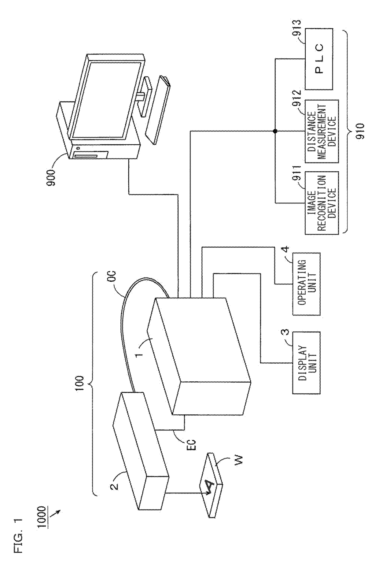
[0049]FIG. 1 is a block diagram illustrating a schematic configuration of a laser processing system according to one embodiment of the present invention. As illustrated in FIG. 1, a laser processing system 1000 includes a laser marking device 100, a laser processing data setting device 900, and a plurality of external devices 910.

[0050]The laser marking device 100 includes a main body 1, a marking head 2, a display unit 3, and an operating unit 4. The main body 1 and the marking head 2 are connected with each other via one electric cable EC ...


PUM

PropertyMeasurementUnit
wavelength regionaaaaaaaaaa
wavelengthaaaaaaaaaa

Abstract

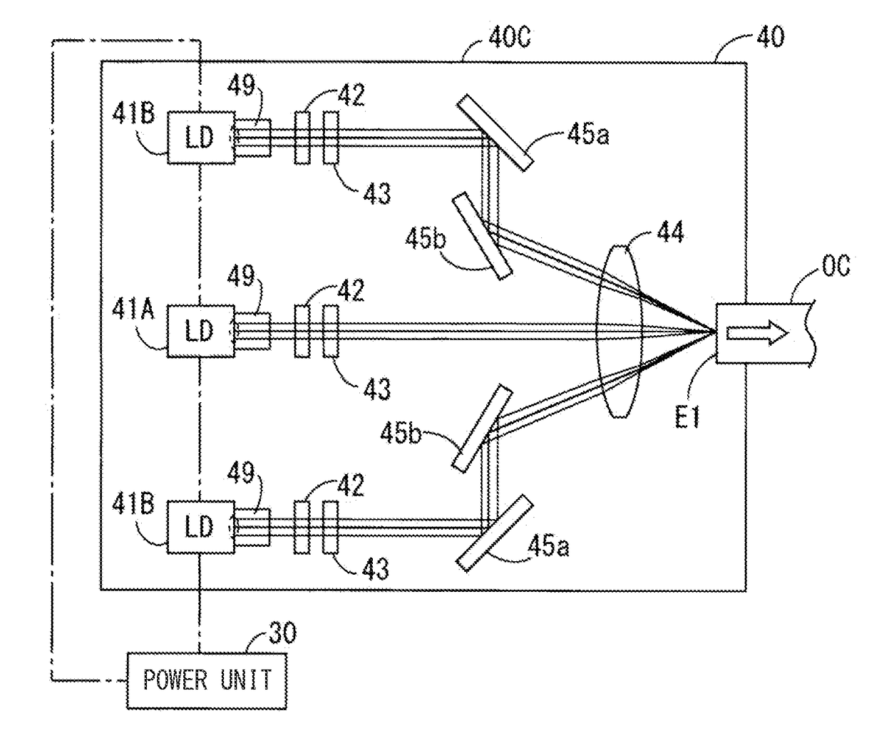
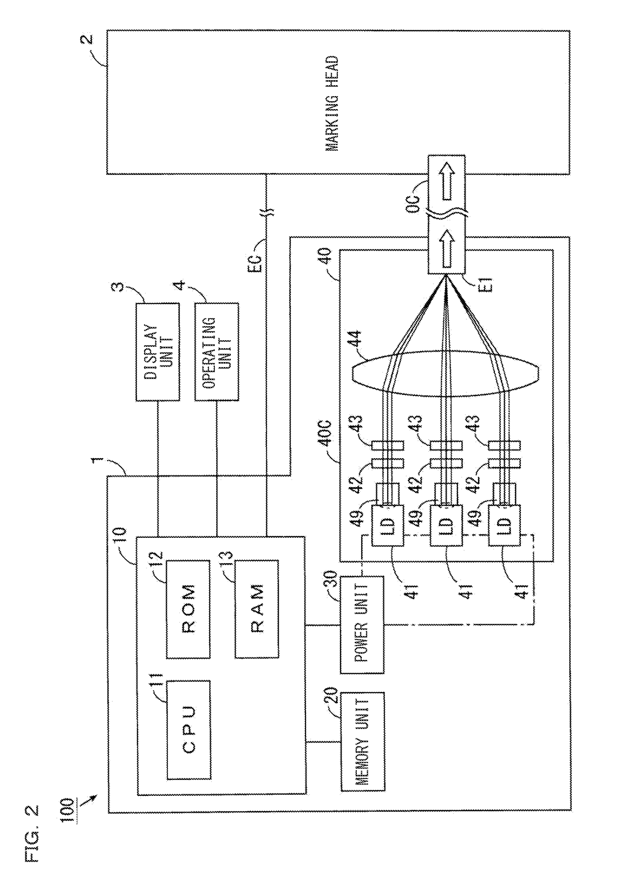
Provided is a laser processing device capable of performing high-power laser processing while preventing reduction of life duration of a light source for excitation light. By collecting the light emitted from single emitters of a plurality of single emitter LDs onto one end face of an optical fiber cable, high-power excitation light is transmitted to a marking head through the optical fiber cable. Excitation light emitted from the other end face of the optical fiber cable is separated into first excitation light and second excitation light. The first excitation light excites a first laser medium to generate laser light. The generated laser light enters a second laser medium. The second excitation light enters the second laser medium. With this, the second laser medium is excited, and the laser light that has entered the second laser medium from the first laser medium is amplified.

Description

CROSS-REFERENCE TO RELATED APPLICATIONS[0001]The present application claims foreign priority based on Japanese Patent Application No. 2014-156572, filed Jul. 31, 2014, the contents of which is incorporated herein by reference.BACKGROUND OF THE INVENTION[0002]1. Field of the Invention[0003]The present invention relates to a laser processing device.[0004]2. Description of Related Art[0005]Conventionally, there is known a laser marking device for two-dimensionally scanning an object (hereinafter referred to as a workpiece) with laser light and thus providing marking for the workpiece in a desired manner (e.g., JP 2008-62258 A). Such a laser marking device includes an oscillator for amplifying excitation light to generate a laser beam.[0006]In the oscillator described in JP 2008-62258 A, a solid such as YAG (yttrium aluminum garnet) or YVO4 (yttrium vanadate) is used as a laser medium.[0007]A gas such as CO2 (carbon dioxide) may also be used as a laser medium of the oscillator. A laser ...

Claims


Application Information

Patent Timeline
Patent Type & Authority Patents(United States)
IPC IPC(8): H01S3/094B23K26/00H01S5/14B23K26/082B23K26/06H01S3/23H01S3/117H01S3/0941B23K26/04H01S5/40H01S3/067B23K26/352B23K26/70B23K26/0622H01S5/00H01S3/16H01S3/00H01S3/10H01S5/06
CPCH01S3/094053B23K26/0066B23K26/048B23K26/0608B23K26/0613B23K26/0624B23K26/082B23K26/352B23K26/706H01S3/0085H01S3/067H01S3/0941H01S3/09415H01S3/117H01S3/2308H01S5/141H01S5/4012H01S5/4018H01S5/4025H01S3/0071H01S3/10061H01S3/1611H01S3/1643H01S3/1673H01S5/0071H01S5/0617H01S5/4062
Inventor SATO, MASAO
Owner KEYENCE
Learn More