Refrigeration process

a refrigeration process and refrigeration technology, applied in refrigeration, lighting and heating equipment, solidification, etc., can solve the problems of not being able to build pipelines in certain environments, not being able to meet the requirements of certain environments, so as to achieve the effect of optimizing the thermodynamic efficiency and improving the efficiency of the compression process

Inactive Publication Date: 2017-02-07
UNIV OF MANCHESTER
View PDF27 Cites 0 Cited by
  • Summary
  • Abstract
  • Description
  • Claims
  • Application Information

AI Technical Summary

Benefits of technology

[0014]The process of the present invention provides a novel mixed refrigerant cycle which provides a balance between thermodynamic efficiency and process complexity, thereby providing a cost effective alternative to the current liquefaction processes. Essentially, the process of the first aspect of the present invention provides the simplicity of a single mixed refrigerant cycle and a single heat exchanger, but provides more operating variables (or “degrees of freedom”) to enable the thermodynamic efficiency of the process to be enhanced.
[0015]In particular, the provision of first and second refrigerant streams of different temperature, pressure and / or composition (as provided in some embodiments of the present invention) in a single cycle mixed refrigerant process provides additional flexibility to enable the thermodynamic efficiency to be optimised. More specifically, this flexibility enables the temperature-enthalpy profile of the refrigerant to be matched to the cooling profile of the feed gas stream as closely as possible.
[0016]Furthermore, the provision of at least two compression steps (namely an initial compression which is only applied to the first refrigerant stream (the lowest pressure stream) exiting the heat exchanger, followed by a second compression applied to the mixture of the compressed first refrigerant stream and the refrigerant of the second refrigerant stream exiting the heat exchanger) enables the compression process to be made more efficient than would be the case if all of the refrigerant exiting the heat exchanger is compressed together.
[0021]The process of the second aspect of the present invention provides a further novel mixed refrigerant cycle which provides a balance between thermodynamic efficiency and process complexity, thereby providing a cost effective alternative to the current liquefaction processes. Essentially, the process of the second aspect of the present invention also provides the simplicity of a single mixed refrigerant cycle, but provides more operating variables (or “degrees of freedom”) to enable the thermodynamic efficiency of the process to be enhanced.
[0024]As for the process of the first aspect of the invention, the provision of first and second refrigerant streams of different temperature, pressure and / or composition (as provided in some embodiments of the present invention) in a single cycle mixed refrigerant process provides additional flexibility to enable the thermodynamic efficiency to be optimised. More specifically, this flexibility enables the temperature-enthalpy profile of the refrigerant to be matched to the cooling profile of the feed gas stream as closely as possible.
[0025]Furthermore, the provision of at least two compression steps (namely an initial compression which is only applied to the first refrigerant stream (the lowest pressure stream) exiting the heat exchanger, followed by a second compression applied to the mixture of the compressed first refrigerant stream and the refrigerant of the second refrigerant stream exiting the heat exchanger) again enables the compression process to be made more efficient than it would be if all of the refrigerant exiting the heat exchanger is compressed together.

Problems solved by technology

The delivery of natural gas from the site of extraction to the end consumer presents a significant logistical challenge.
Pipelines can be used to transport natural gas over short distances (typically less than 2000 km in offshore environments and less than 3800 km in onshore environments), but they are not an economical means of transport when larger distances are involved.
Furthermore, it is not practical to build pipelines in certain environments, such as, for example, across large expanses of water.
These refrigeration cycles can be extremely energy intensive, primarily due to the amount of shaft power input required to run the refrigerant compressors.
One problem with such processes is that they exhibit lower thermodynamic efficiency relative to more complex processes (e.g. the propane-cooled mixed refrigerant cycle by Air products, or the double mixed refrigerant cycle by Shell).
Furthermore, the thermodynamic performance and efficiency of a single mixed refrigerant cycle can only be varied by adjusting a small number of operating variables, such as the refrigerant composition, the condensation and evaporation temperature and the pressure level.
However, multi-stage or cascade refrigeration processes usually require much more complicated equipment configurations, and this results in significant plant and equipment costs.

Method used


Image

  • Refrigeration process
  • Refrigeration process
  • Refrigeration process

Examples


example

Process Modelling and Optimisation

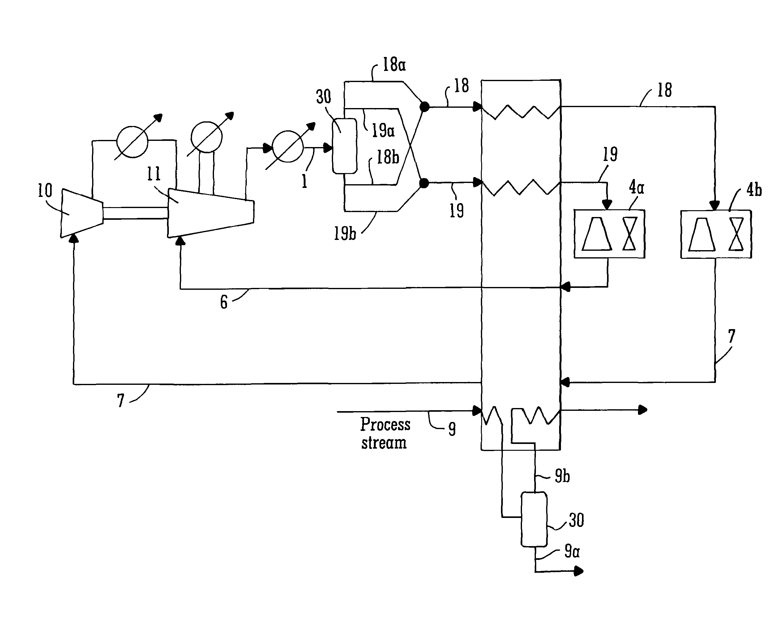
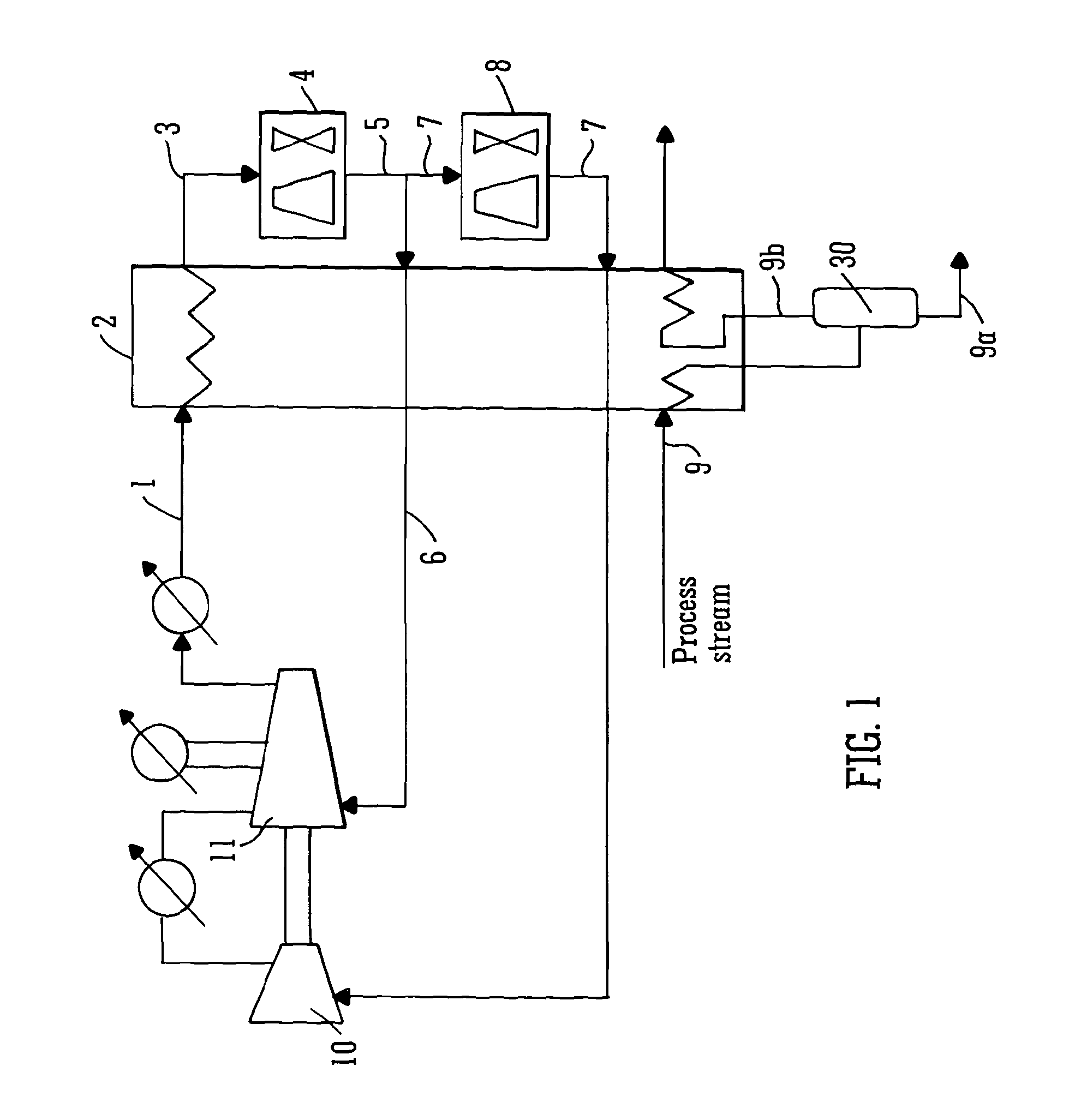
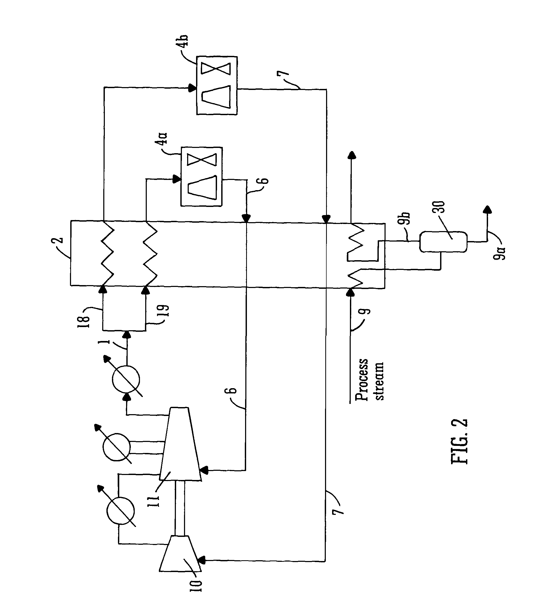
[0167]For each embodiment described above in reference to FIGS. 1 to 4, the independent variables in the process are identified first, and then physical property calculations, mass balance and energy balances are implemented to compute other intermediate operating conditions and evaluate the overall performance of the refrigeration process. The physical property calculation is based on Equation of State (for example, Peng-Robinson method) which provides thermodynamic information between stream conditions (composition, temperature, pressure) and physical properties (enthalpy, entropy). In principle, once the composition is given, the physical state of a stream is determined by any two of the following parameters: temperature, pressure, specific enthalpy and specific entropy. This feature is utilised to calculate stream enthalpy change in the heat exchanger, and to determine the stream conditions after expansion and compression. If stream mixing or sp...

case study 1

[0177]A pre-treated natural gas stream is to be cooled from 19.85° C. to −58.15° C. using a mixture of hydrocarbons C2H6, C3H8, and n-C4H10 as the refrigerant components. The objective is to minimise the compression power consumption. External cold utility is available to cool hot refrigerant to 40° C. The minimum temperature difference for feasible heat transfer is 2.5° C. Compressor isentropic efficiency is assumed to be 80%. To be consistent with previous work by Vaidyaraman et al. (2002), physical property calculations are conducted with SRK (Soave-Redlich-Kwong) equation of state. The temperature-enthalpy profile of the natural gas stream is given in Table 1.

[0178]

TABLE 1Temperature-enthalpy profile of the natural gas stream.Temperature (° C.)Enthalpy (kW)19.853969.83811.523608.9433.263248.05−4.922887.157−12.972526.262−20.862165.368−28.551804.474−35.981443.579−41.451167.567−42.781082.685−48.27721.791−53.42360.896−58.150

[0179]A conventional single mixed cycle and all the novel r...

case study 2

[0192]In this study, existing processes as well as the four embodiments of the present invention, were optimised for LNG production. A pre-treated natural gas stream is to be cooled from ambient temperature 25° C. to −163° C. A mixture of hydrocarbons CH4, C2H6, C3H8, n-C4H10 and N2 is employed as the mixed refrigerant. The objective was to minimise the compression power consumption based on multi-stage compression. External cold utility is available to cool hot refrigerant down to 30° C. The minimum temperature difference for heat transfer is 5° C. Compressor isentropic efficiency is assumed to be 80%. The physical property calculations are performed based on Peng-Robinson equation of state. The temperature-enthalpy profile of the natural gas stream is given in Table 4.

[0193]

TABLE 4Temperature-enthalpy profile of the natural gas stream.Temperature (° C.)Enthalpy (kW)2520178.8−6.0318317−34.0916352.8−57.6514468−70.111978−74.5510198−82.267114−96.55690−1153840−1630

[0194]In order to hav...


PUM


Abstract

The present invention relates to a single cycle mixed refrigerant process for industrial cooling applications, for example, the liquefaction of natural gas. The present invention also relates to a refrigeration assembly configured to implement the processes defined herein and a mixed refrigerant composition usable in such processes.

Description

CROSS-REFERENCE TO RELATED APPLICATIONS[0001]This application is the National Phase of International Application PCT / GB2011 / 050617, filed Mar. 25, 2011, which designated the United States and that International Application was published under PCT Article 21(2) in English. This application also includes a claim of priority under 35 U.S.C. §119(a) and §365(b) to PCT / GB2011 / 050444 filed Mar. 7, 2011 and British patent application No. 1005016.9 filed Mar. 25, 2010.[0002]This invention relates to a refrigeration process and, more particularly but not exclusively, to a refrigeration process that is suitable for the liquefaction of natural gas.BACKGROUND[0003]The delivery of natural gas from the site of extraction to the end consumer presents a significant logistical challenge. Pipelines can be used to transport natural gas over short distances (typically less than 2000 km in offshore environments and less than 3800 km in onshore environments), but they are not an economical means of trans...

Claims


Application Information

Patent Timeline
Patent Type & Authority Patents(United States)
IPC IPC(8): F25J1/00F25J1/02
CPCF25J1/0022F25J1/0012F25J1/0015F25J1/0017F25J1/0027F25J1/0052F25J1/0055F25J1/0057F25J1/0092F25J1/0212F25J1/0214F25J1/0245F25J1/0249F25J1/0252F25J1/0278F25J2220/64F25J2245/02F25J2270/12F25J2270/14F25J2270/16F25J2270/66
Inventor KIM, JIN-KUKZHENG, XUESONG
Owner UNIV OF MANCHESTER
Why Eureka
Try Eureka