
Process for producing fluorinated ion exchange resin fluid

a technology of ion exchange resin and process, which is applied in the manufacture of final products, cell components, electrochemical generators, etc., can solve the problems of gas leakage, incomplete adhesion to the catalyst layer, and deterioration of the polymer electrolyte membrane or the catalyst layer, etc., to achieve good durability, good durability, and less wrinkles

Active Publication Date: 2016-12-27
ASAHI GLASS CO LTD
View PDF22 Cites 2 Cited by
  • Summary
  • Abstract
  • Description
  • Claims
  • Application Information

AI Technical Summary

Benefits of technology

The present invention is a process for producing a fluorinated ion exchange resin fluid, which is useful for making a polymer electrolyte membrane for a fuel cell. The process allows for the production of a membrane with good durability and minimal wrinkles. This invention also provides a process for forming a catalyst layer that is durable and wrinkle-free, and a membrane / electrode assembly for a polymer electrolyte fuel cell that has good durability and power generation properties.

Problems solved by technology

If the fluorinated ion exchange resin contains organic substances other than the fluorinated ion exchange resin, as impurities, the durability of the polymer electrolyte membrane or the catalyst layer deteriorates.
However, the method for immersing the polymer electrolyte membrane in an aqueous hydrogen peroxide solution has the following problems.
If wrinkles are formed on the polymer electrolyte membrane, the adhesion to the catalyst layer tends to be incomplete, and gas is likely to leak at the interface between the catalyst layer and the polymer electrolyte membrane, whereby the power generation properties of the membrane / electrode assembly tend to be inadequate.

Method used


Image

  • Process for producing fluorinated ion exchange resin fluid
  • Process for producing fluorinated ion exchange resin fluid
  • Process for producing fluorinated ion exchange resin fluid

Examples


example 1

Preparation of Fluorinated Ion Exchange Resin Fluid

Step (β1):

[0340]Polymer (F1-1) (copolymer of TFE and monomer (m1-1), ion exchange capacity after hydrolysis: 1.1 meq / g dry resin) was put into an extruder and extruded from a die having a hole of 4 mm in diameter and heated to 200° C. and pulled at a rate slightly higher than the extrusion rate and cooled, followed by cutting by a pelletizer to obtain pellets of polymer (F1-1) having a cross-sectional diameter of from 1 to 3 mm and a length of from 5 to 20 mm.

Step (β2):

[0341]450 g of the pellets of polymer (F1-1) were put into a reactor made of glass and having an internal capacity of 2.5 L, and 0.68 kg of an aqueous potassium hydroxide solution having a concentration of 48 mass %, 0.44 kg of methanol and 1.0 kg of ultrapure water were put, and the temperature was raised with stirring until the internal temperature became 90° C., and while controlling the temperature to be ±3° C., the system was maintained for 16 hours. Thereafter, ...

example 2

Production of Fluorinated Ion Exchange Resin Fluid

Step (α1):

[0357]Pellets of polymer (F1-1) having a cross-sectional diameter of from 1 to 3 mm and a length of from 5 to 20 mm, obtained in step (β1) in Example 1, were prepared.

Step (α2):

[0358]Pellets of salt-form polymer (H1-1) were obtained by carrying out hydrolytic treatment in the same manner as step (β2) in Example 1.

Step (α3):

[0359]Into the reactor, 2.0 kg of ultrapure water was put, the temperature was raised to 85° C., and stirring was carried out for one hour, and then, the temperature was lowered, and water was discharged. Such an operation was repeated ten times in total. The pH of the water discharged the 10th time was confirmed to be 8.

Step (α4):

[0360]Pellets of hydrogen peroxide-treated salt-form polymer (H1-1) were obtained by carrying out hydrogen peroxide treatment in the same manner as step (β6) in Example 1.

Step (α5):

[0361]Washing with water was carried out in the same manner as step (β7) in Example 1.

Step (α6):

[0...

example 3

Production of Fluorinated Ion Exchange Resin Fluid

Step (α1):

[0370]Pellets of polymer (F1-1) having a cross-sectional diameter of from 1 to 3 mm and a length of from 5 to 20 mm, obtained in step (β1) in Example 1, were prepared.

[0371]The pellets of polymer (F1-1) were put into a pulverizer (manufactured by HORAI Co, Ltd.) and pulverized to a level of from 0.5 to 2 mm to obtain a powder of polymer (F1-1).

Steps (α2) to (α8):

[0372]A fluorinated ion exchange resin fluid (L-3) having a solid content concentration of 28 mass %, was obtained in the same manner as steps (α2) to (α8) in Example 2 except that instead of the pellets of polymer (F1-1), the powder of polymer (F1-1) was used.

(Formation of Polymer Electrolyte Membrane)

[0373]A polymer electrolyte membrane (M-3) was obtained in the same manner as in Example 1 except that instead of the fluorinated ion exchange resin fluid (L-1), the fluorinated ion exchange resin fluid (L-3) was used. No wrinkles were observed on the polymer electrol...


PUM

PropertyMeasurementUnit
lengthaaaaaaaaaa
lengthaaaaaaaaaa
mass %aaaaaaaaaa

Abstract

To provide a process for forming a polymer electrolyte membrane having good durability and few wrinkles, a polymer electrolyte membrane capable of forming a catalyst layer, or a catalyst layer; a process for producing a fluorinated ion exchange resin fluid, or a paste for forming a catalyst layer, which can be used for such a forming process; and a process for producing a membrane / electrode assembly for a polymer electrolyte fuel cell having good durability and power generation properties. A fluorinated ion exchange resin fluid obtained by subjecting a powder or pellets of a fluorinated ion exchange resin having cation exchange groups to hydrogen peroxide treatment, followed by mixing with a solvent, is used.

Description

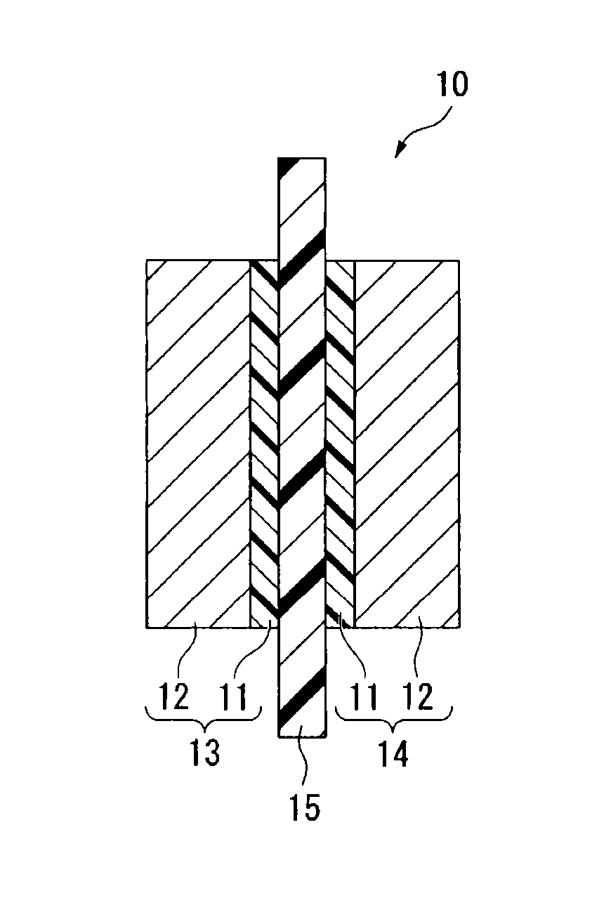
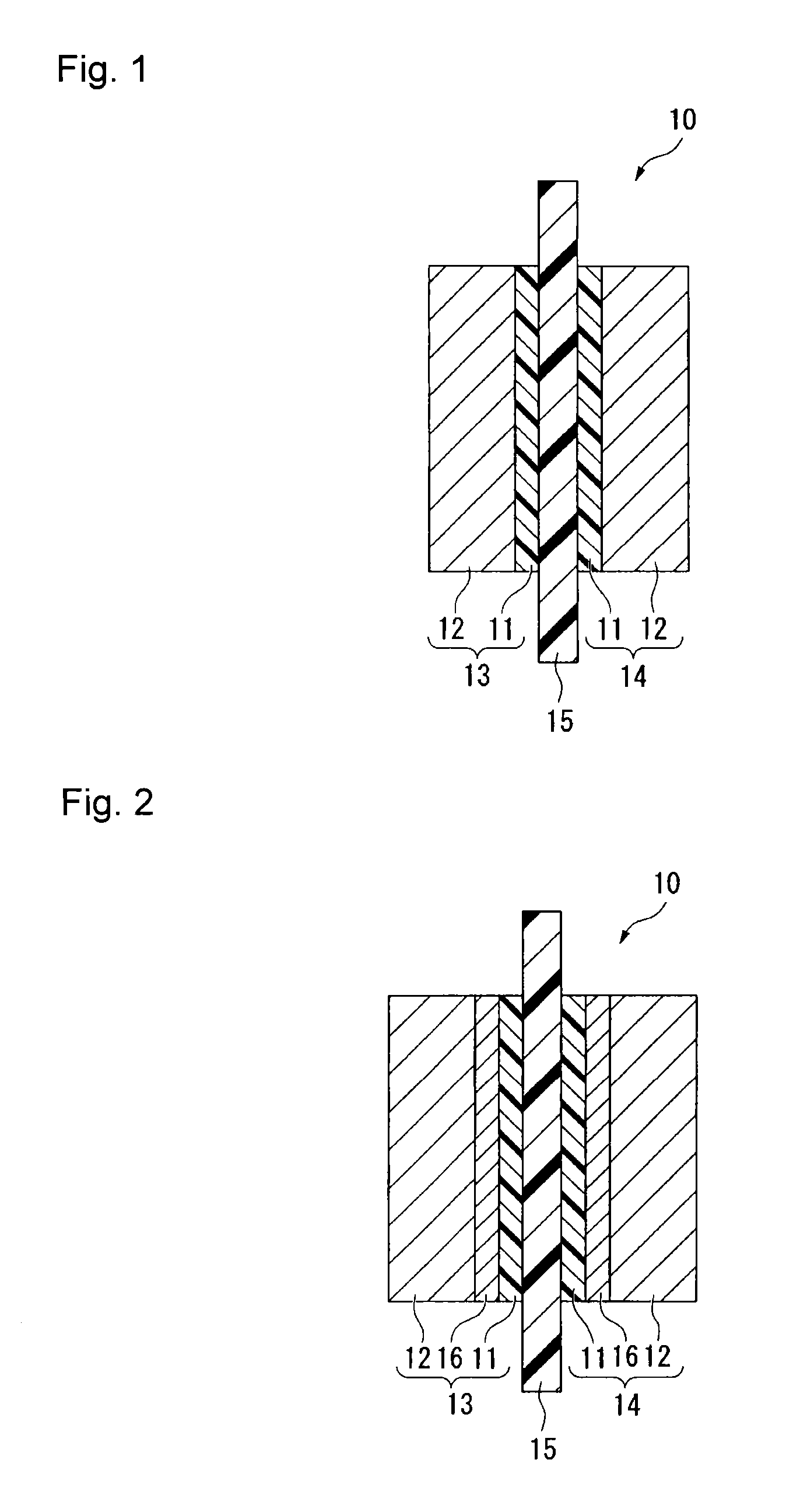
TECHNICAL FIELD[0001]The present invention relates to a process for producing a fluorinated ion exchange resin fluid and a process for forming a polymer electrolyte membrane by using it; a process for producing a paste for forming a catalyst layer and a process for forming a catalyst layer by using it; and a process for producing a membrane / electrode assembly for a polymer electrolyte fuel cell.[0002]A polymer electrolyte fuel cell is, for example, a stack of a plurality of cells each comprising a membrane / electrode assembly sandwiched between two separators. The membrane / electrode assembly is one comprising an anode and a cathode each having a catalyst layer and a gas diffusion layer, and a polymer electrolyte membrane disposed between the anode and the cathode. The catalyst layer and the polymer electrolyte membrane contain a fluorinated ion exchange resin having acid-form cation exchange groups.[0003]If the fluorinated ion exchange resin contains organic substances other than the...

Claims


Application Information

Patent Timeline
Patent Type & Authority Patents(United States)
IPC IPC(8): H01M8/1018H01M8/10H01M4/86
CPCH01M8/1018H01M8/1023H01M8/1039H01M8/1072H01M4/8663Y02E60/521Y02P70/56Y02E60/50Y02P70/50H01M4/8825H01M8/1004H01M8/1069
Inventor WAKABAYASHI, HIROKAZUHOMMURA, SATORUSAEKI, TAKASHISHIMOHIRA, TETSUJI
Owner ASAHI GLASS CO LTD
Learn More