Grout removal and masonry trenching tool

a technology of grout removal and masonry trenching, which is applied in the direction of carpet cleaners, other artistic work equipments, decorative arts, etc., can solve the problems of grout discolouration and breakage, process requires significant effort, and grout can become discoloured and susceptible to breakag

Active Publication Date: 2016-12-06
TAYLOR IAN RONALD
View PDF72 Cites 2 Cited by
  • Summary
  • Abstract
  • Description
  • Claims
  • Application Information

AI Technical Summary

Benefits of technology

[0012]In accordance with another aspect of the invention, but not necessarily the broadest aspect, there is proposed a tool for dislodging grout from a joint between two adjacent planar surfaces, or for removing a strip of material from a masonry surface including, a generally elongate body having a lower portion dimensioned to fit at least partially within a channel created by a first cutting tip of a first blade or edge, the first cutting tip forwardly facing for impinging upon and dislodging material, a guide forward of said first blade or edge for controlling the depth to which said first blade or edge penetrates said grout or said masonry surface, and a front portion of said tool being curved upwardly, said front portion including a second blade or edge having a leading secondary cutting tip or edge, whereby the rear of the tool may be pivoted upward about the leading edge of said tool to utilise said secondary cutting tip or edge to dislodge said material without being inhibited or obstructed by said guide.
[0013]The underside of the first blade or edge rearward of the first cutting tip is relieved at an angle upward from the grout or masonry surface to allow the first cutting tip to penetrate the surface. The area of the main body of the tool behind the first cutting tip is also relieved, so as to allow the tip to penetrate the surface when commencing, once the tip has penetrated the surface the guide controls the depth of the first cutting tip.
[0015]In this way the first blade or edge can be used to remove the grout in open areas away from the corners of the room. The guide that is positioned forwards of the first blade or edge controls the depth to which the forwardly facing cutting edge penetrates the grout. It is envisaged that the guide will be predominantly a depth control means.
[0016]When a user wants to remove grout from a confined space or in areas close to the perpendicular junction between two surfaces such as where a wall meets the floor the tool can be pivoted up, rotated or otherwise moved so the second blade or edge can be used without being obstructed by the depth guide. As the reader will appreciate in this second orientation the tip of the cutting edge of said second blade or edge projects forward of the body and therefore the user can remove material from the joint without being hindered by the guide.
[0019]The lower horizontal edge of the guide may act to direct the first blade or edge to inhibit it from disengaging from within the joint. The guide may also act as a depth gauge to inhibit the first blade or edge from penetrating into the joint to a point where it impinges upon the underlying surface of the wall or floor. Typically in the case of grout removal, it will not be necessary to remove grout below the thickness of the tile as the user will either re-grout or remove damaged tiles. However it will be appreciated that contact with the underlying surface could damage or hasten wear of the blade or edge if the surface is hard, such as concrete. Alternatively, if the underlying surface is cladding, such as blue board, the integrity of the surface may be damaged.
[0025]In an alternate form the first and second blades may be reversibly attached to the body. In this way when the blades are worn or damaged they can be replaced, the second blade would likely be replaced with less frequency than the first blade as it is only used in certain circumstances and therefore the blades could be replaced separately.

Problems solved by technology

One of the problems with this type of construction material is that it is porous, which means it can discolour and break down over time.
In situations where sealers have not been used or the sealer has degraded over time, the grout can become discoloured and be susceptible to break down by the action of mould or moisture.
This process requires significant effort and the user must concentrate to ensure that the blade or edge does not jump out from within the joint therefore scratching the tile surface.
It is also difficult to use the currently available tools to remove grout from joints in confined locations.
Furthermore the currently available tools do not control the depth to which the tool can penetrate the surface thereby the operator must pay particular attention to the depth the tool has penetrated the surface.
Using a hammer and chisel labour is intensive and risks injury and / or unsatisfactory out-comes due to operator fatigue and loss of concentration.
Both methods require the operator to control the depth potentially damaging the integrity of the masonry construction.

Method used


Image

  • Grout removal and masonry trenching tool
  • Grout removal and masonry trenching tool
  • Grout removal and masonry trenching tool

Examples


Embodiment Construction

[0058]There are numerous specific details set forth in the following description. However, from the disclosure, it will be apparent to those skilled in the art that modifications and / or substitutions may be made without departing from the scope and spirit of the invention. In some circumstances specific details may have been omitted or enlarged so as not to obscure the invention. Similar reference characters indicate corresponding parts throughout the drawings.

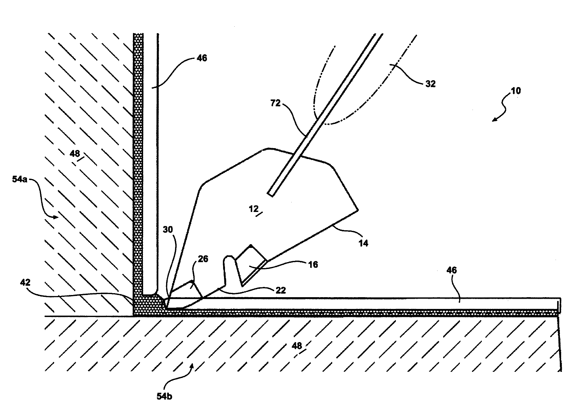
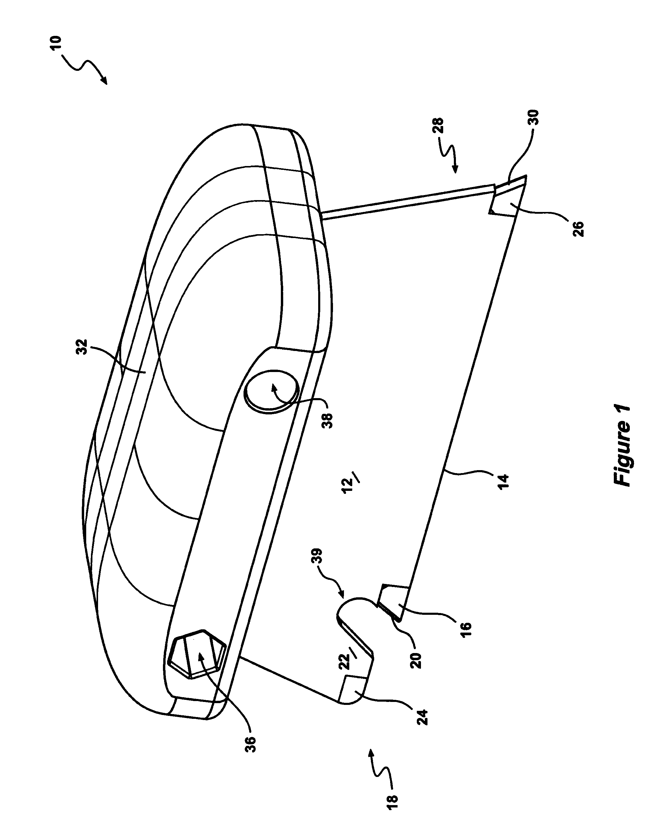
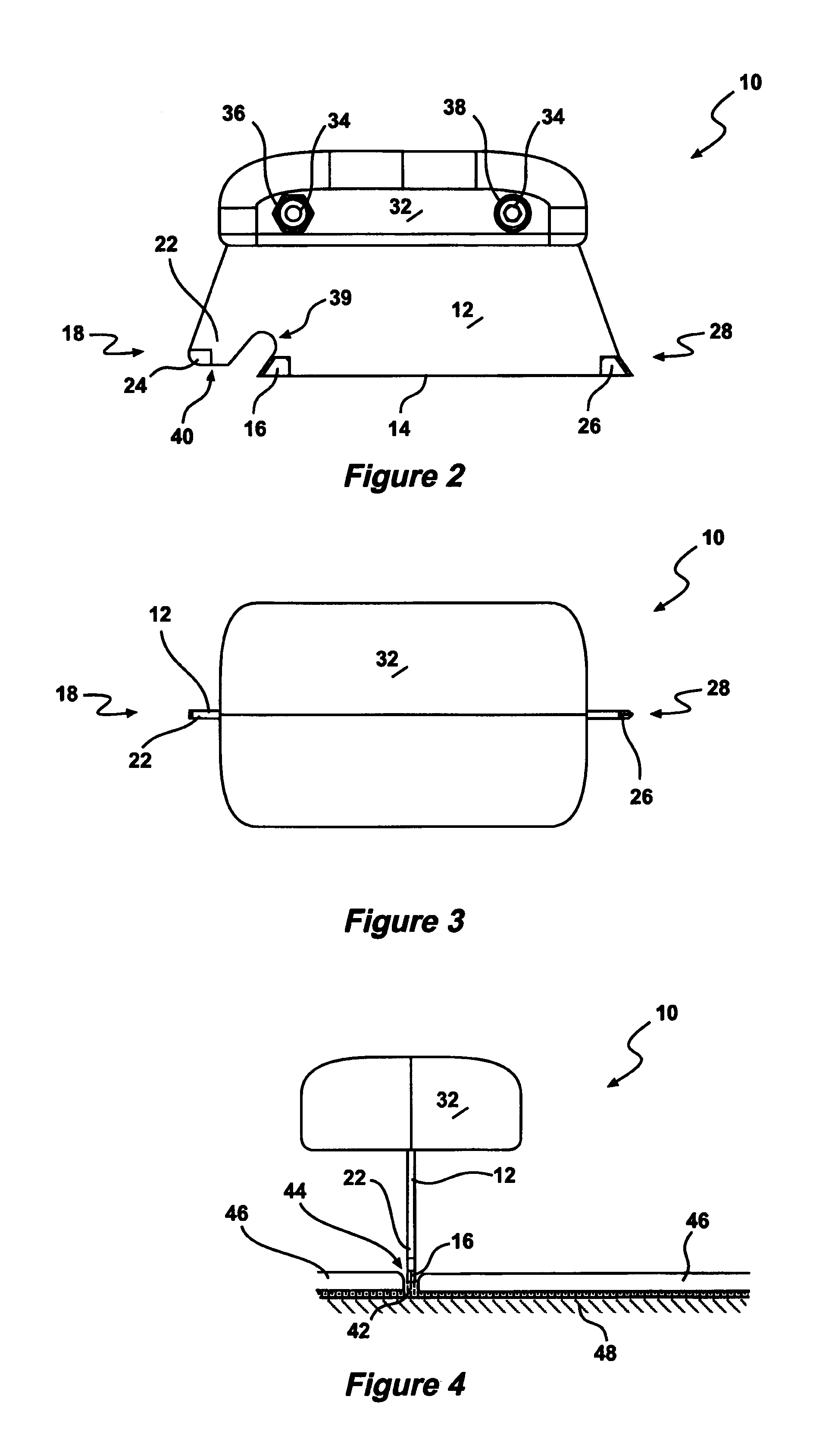
[0059]The tool 10 of the present invention has a number of uses. In the first embodiment it may be used as a grout removing device having a cutting tip between 1.0 mm-5.0 mm wide. In a second embodiment the tool 10 may be attached to, or comprise a lightweight electric impact chisel, or may be a hand operated tool. The tool 10 may also be used for heavy-duty use in the process of grooving, trenching or chasing in masonry, brickwork or wall plaster for electrical cable or water pipes etc.

[0060]In one embodiment, the tool may be...


PUM

PropertyMeasurementUnit
angleaaaaaaaaaa
depthaaaaaaaaaa
distanceaaaaaaaaaa

Abstract

A tool for dislodging grout from a joint between two adjacent planar surfaces, or for removing a strip of material from a masonry surface including, a generally elongate body having a lower portion dimensioned to fit at least partially within a channel created by a first cutting tip of a first blade or edge, the first cutting tip forwardly facing for impinging upon and dislodging material, a guide forward of said first blade or edge for controlling the depth to which said first blade or edge penetrates said grout or said masonry surface, and a front portion of said tool being curved upwardly, said front portion including a second blade or edge having a leading secondary cutting tip, whereby the rear of the tool may be pivoted upward about the leading edge of said tool to utilise said secondary cutting tip to dislodge said material without being inhibited or obstructed by said guide.

Description

CROSS REFERENCE TO RELATED APPLICATIONS[0001]This application is a national stage application under 35 U.S.C. 371 and claims the benefit of PCT Application Ser. No. PCT / AU2011 / 001564 having an international filing date of 2 Dec. 2011, which designated the United States, and which PCT application claimed the benefit of Australian Application No. 2010905283 filed 1 Dec. 2010, the disclosure of which is incorporated herein by reference.FIELD OF THE INVENTION[0002]The present invention relates to a grout removing and masonry trenching or chasing device, and in one aspect relates to a tool including first and second cutting blades or edge and a depth control guide associated with the first blade or edge.BACKGROUND OF THE INVENTION[0003]Grout is a construction material used to seal joints between wall tiles and floor tiles. Grout is typically composed of a mixture of water, cement, sand, and a colour tint. The grout is applied to the joints as a viscous material and hardens over a short p...

Claims


Application Information

Patent Timeline
Patent Type & Authority Patents(United States)
IPC IPC(8): E04F21/00A47L13/08B28D1/18B28D1/22B44D3/16
CPCE04F21/0084A47L13/08B28D1/183B28D1/228B44D3/162
Inventor TAYLOR, IAN RONALD
Owner TAYLOR IAN RONALD
Why Eureka
Try Eureka