
Dual focusing optical coherence imaging system

a coherence imaging and optical coherence technology, applied in the field of optical coherence imaging systems, can solve the problems of physical inability to acquire video information with respect to the cornea, inability to measure the cornea and the retina at the same time using a single spectrometer, and inability to achieve simultaneous measurement of cornea and retina that have different focused areas, etc., to achieve simple and easy way to achieve image signal distortion prevention, compact system cost, and easy to use

Active Publication Date: 2016-11-15
KOREA UNIV RES & BUSINESS FOUND
View PDF7 Cites 0 Cited by
  • Summary
  • Abstract
  • Description
  • Claims
  • Application Information

AI Technical Summary

Benefits of technology

[0045]The dual focusing optical coherence imaging system according to the present invention as constructed above have the following advantages.
[0046]First, the dual focusing optical coherence imaging system according to the present invention enables the simultaneous or alternative acquisition of the video information on the different focused areas of a single to-be-detected object through a single scan operation performed on the single to-be-detected object.
[0047]Second, the dual focusing optical coherence imaging system according to the present invention enables the simultaneous or alternative acquisition of the video information on the different focused areas of a retina and cornea of an eyeball as the to-be-detected object through a single scan operation.
[0048]Third, the dual focusing optical coherence imaging system according to the present invention enables the simultaneous or alternative acquisition of the images on the different focused areas of the to-be-detected object to acquire an interference signal for the to-be-detected object through a switching operation based on a sequential or preset manner by an optical switch, thereby achieving compactness and the manufacturing cost of the system.
[0049]Fourth, the dual focusing optical coherence imaging system according to the present invention enables the simultaneous or alternative acquisition of the images on the different focused areas of the to-be-detected object to acquire an interference signal for the to-be-detected object through a switching operation based on a sequential or preset manner by an optical switch, so that the number of the spectrometers can be reduced to a single number, thereby providing the effects of preventing distortion of the image signal, processing a trigger signal in a simple and easy manner, and minimizing the measurement time owing to unnecessity of a video signal calibration algorithm based on software / hardware.
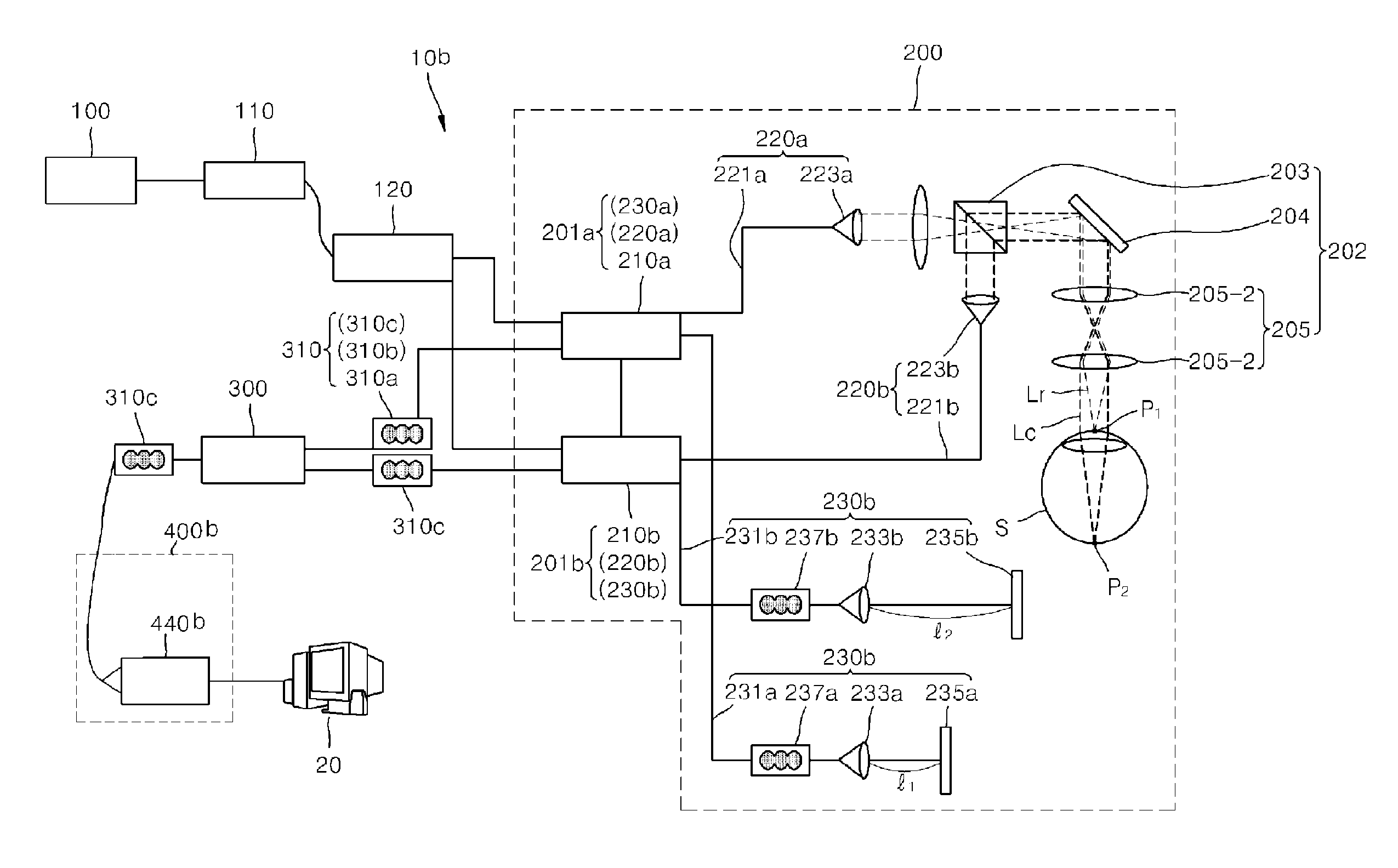
[0050]Fifth, the dual focusing optical coherence imaging system according to the present invention enables the simultaneous measurement of the cornea and the retina through a sample arm by irradiating a focused light onto the cornea to measure the cornea through hardward-based technological modification of the system, and at the same time irradiating parallel light onto the eyeball to measure the retina, so that the simultaneous measurement of the cornea and the retina can be made by the sample arm, and the position of a reference mirror for measurement of the cornea and the position of a reference mirror for measurement of the retina are fixed separately using two optical fiber distributors (or fiber couplers), thereby simultaneously acquiring individual diagnosis video information on the cornea and the retina by controlling the travel distance of the light from an optical fiber distributor

Problems solved by technology

In addition, researches are overly actively in progress on technologies for allowing the image acquiring speed to be made fast, acquiring high resolution images, reducing the manufacturing cost, minimizing the influence of noises, and so forth.
There frequently occurs the case where the cornea and the retina are required for evaluation and diagnosis, but an OCT technology has not been proposed yet which can measure the cornea and the retina simultaneously.
That is, in case of the conventional OCT system for ophthalmic use, since the position of the mirror of the reference arm is fixed so that an image is acquired at a portion where a single focal point is formed by the lens of the sample arm, it is impossible to simultaneously measure the cornea and the retina that have different focused areas using a single spectrometer.
The reason for this is that when the position of the mirror of the reference arm is set based on the focal formation distance of the retina, acquisition of video information with respect to the cornea is physically impossible due to a significant difference between the light travel distance from the optical distributor to the retina the light travel distance from the optical distributor to the cornea.
Further, the cornea is positioned in front of the crystalline lens in the eyeball, and the retina is positioned at the rear of the crystalline lens in the eyeball, so that when the parallel light is transmitted to the retina to acquire an image of the retina, a focus is not formed at the cornea, which makes it impossible to acquire an image of the cornea.
Thus, an existing OCT system entails a problem in that it is designed for measurement of either the retina or the cornea, and two spectrometers are needed to solve this, leading to an increase in the number of the spectrometers, and thus a sharp increase in the manufacturing cost.
This makes it difficult to achieve a compact structure of the OCT system.

Method used


Image

  • Dual focusing optical coherence imaging system
  • Dual focusing optical coherence imaging system
  • Dual focusing optical coherence imaging system

Examples


Embodiment Construction

[0067]Now, preferred embodiments of a dual focusing optical coherence imaging system according to the present invention will be described hereinafter in detail with reference to the accompanying drawings.

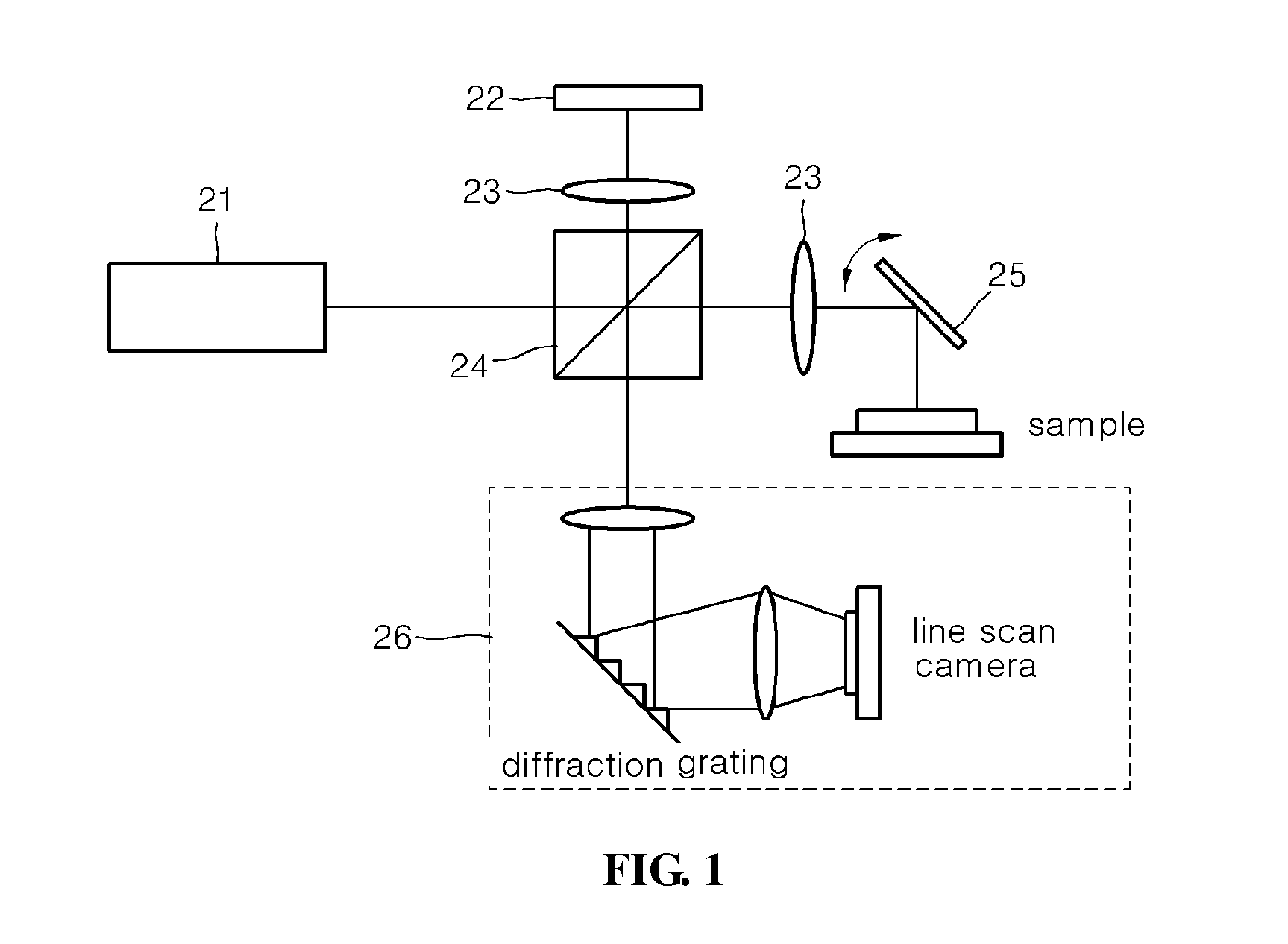
[0068]FIG. 1 is a basic schematic view illustrating an optical coherence tomography (SD-OCT) system according to the prior art, FIG. 2 is a schematic block diagrammatic view illustrating a dual focusing optical coherence imaging system according to one embodiment of the present invention, FIG. 3 is a schematic state view illustrating an eyeball as an object to be detected in a dual focusing optical coherence imaging system according to an embodiment of the present invention, FIG. 4 is a schematic block diagrammatic view illustrating additional constituent elements of a dual focusing optical coherence imaging system according to an embodiment of the present invention, FIG. 5 is a schematic block diagrammatic view illustrating another example of a dual focusing optical coherence imagi...


PUM


Abstract

The present invention relates to a dual focusing optical coherence imaging system. The dual focusing optical coherence imaging system includes: a light source unit for generating broadband light; a main optical distributor for distributing the light generated from the light source to allow the light to be propagated; an interference unit including first and second interference parts for forming interference signals with respect to different focused areas of an object to be detected using the light distributed from the optical distributor, and a common sample arm commonly connected to the first and second interference parts; an optical switch connected to the first and second interference parts to select at least one of the interference signals transmitted from the first and second interference parts; and a detection unit for converting the interference signal selected by the optical switch according to a preset mode into an electrical signal.

Description

TECHNICAL FIELD[0001]The present invention relates to an optical coherence imaging system, and particularly to, an optical coherence imaging system configured to have a compact structure, which enables acquisition of video information for a plurality of focused areas of a single object to be detected through a single scan operation.BACKGROUND ART[0002]In general, an optical coherence tomography (OCT) is one of advanced medical imaging technologies that currently come into the significant spotlight in the market. The optical coherence tomography (OCT) possesses a representative advantage in that it can perform a tomographic imaging of the inner microstructure of a biological tissue with a micro-high definition in a non-invasive and high-speed manner. Since an optical coherence tomography (OCT) for ophthalmic use for imaging of a retina was greatly successful in commercialization, the speed of the research has been accelerated on commercialization of various OCT-related products inclu...

Claims


Application Information

Patent Timeline
Patent Type & Authority Patents(United States)
IPC IPC(8): A61B3/14A61B3/10G01B9/02A61B5/00
CPCA61B3/102A61B5/0066G01B9/02021G01B9/02027G01B9/02044G01B9/02091
Inventor KIM, BEOP MINJEONG, HYUN WOOLEE, SANG WON
Owner KOREA UNIV RES & BUSINESS FOUND
Learn More