Displacement sensor, spectral characteristic measuring apparatus, color measuring apparatus, planar measured object quality monitoring apparatus, displacement measuring method, spectral characteristic measuring method, and color measuring method
a technology of displacement sensor and spectral characteristic, which is applied in the direction of optical radiation measurement, instruments, spectrometry/spectrophotometry/monochromators, etc., can solve the problem of difficulty in maintaining a horizontal position of paper
- Summary
- Abstract
- Description
- Claims
- Application Information
AI Technical Summary
Benefits of technology
Problems solved by technology
Method used
Image
Examples
first embodiment
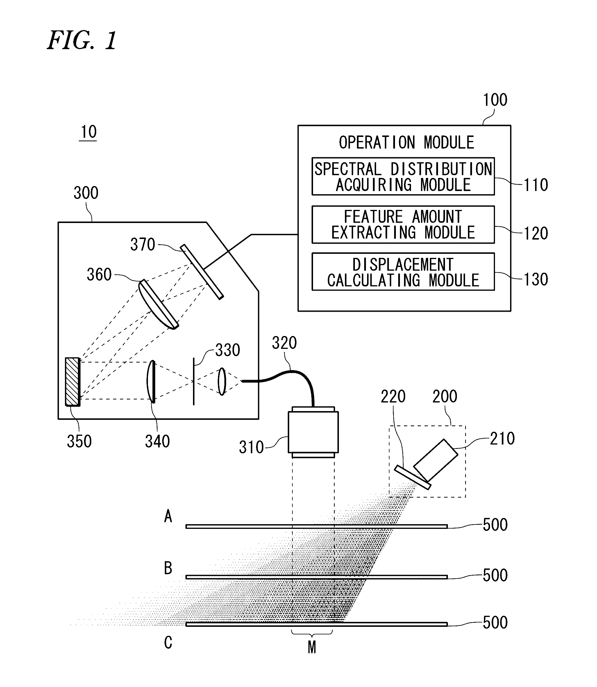
[0090]Exemplary embodiments of the invention will be described with reference to the drawings. FIG. 1 is a diagram describing a displacement sensor according to a As shown in FIG. 1, a displacement sensor 10 is an apparatus for measuring displacement of a measured object using a spectroscope, and includes an operation module 100, a light source unit 200 and a spectroscope 300.
[0091]In the first embodiment, a paper 500 as the measured object will be described, but the displacement sensor 10 is suitable to measure displacement of a film or other planar objects. As long as the measured object is the planar object, the measured object is not limited to continuous objects and the embodiment can be applied to measurement of displacement of a small piece or a portion of the apparatus.
[0092]In the displacement sensor 10, a region with a desired size in the planar measured object is targeted for measurement of displacement and this region is called a measurement region M. Since a region hav...
second embodiment
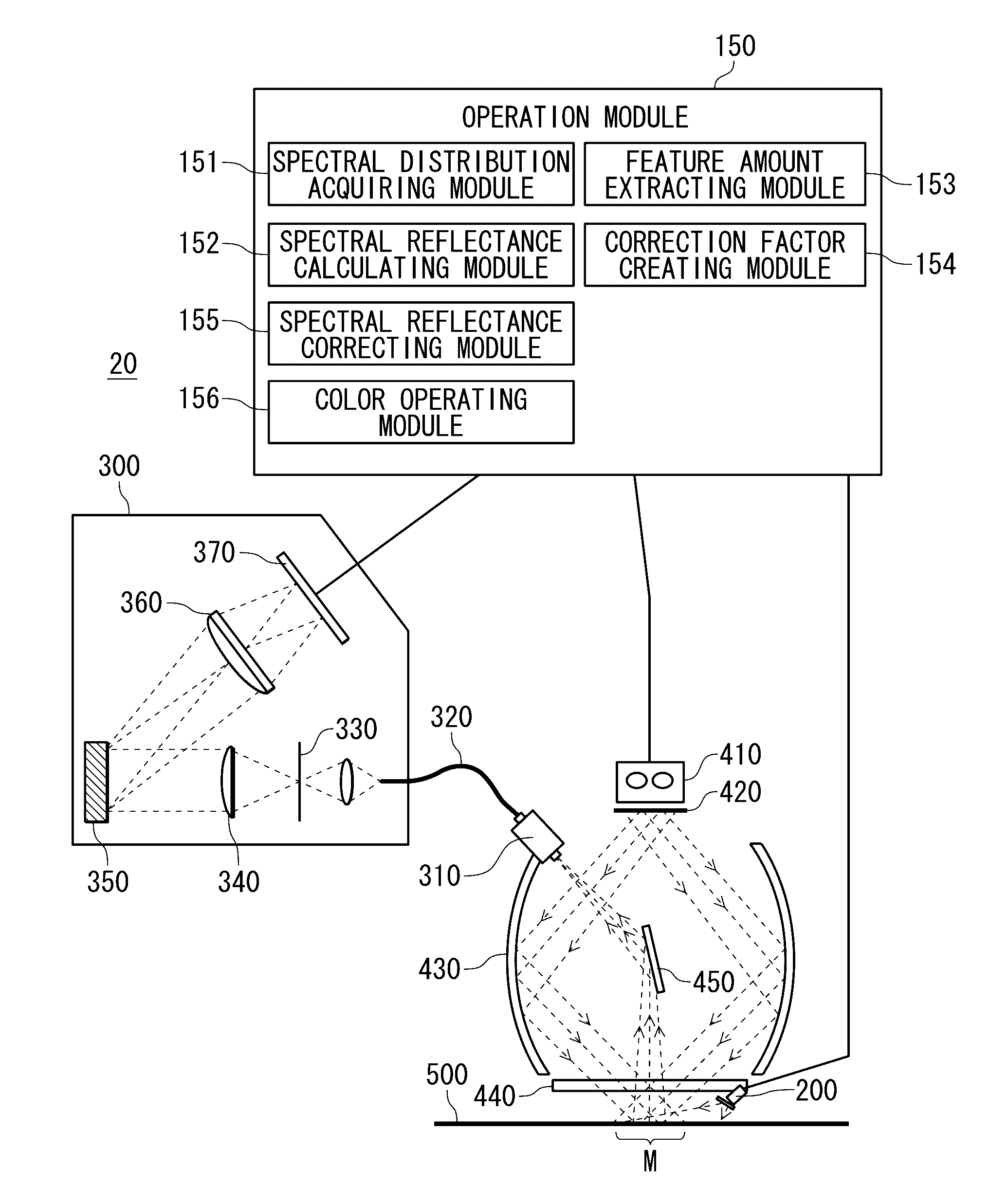
[0133]In addition, in the second embodiment described above, the wavelength range of spectral distribution for measurement is set at 400 nm to 700 nm and the wavelength range of spectral distribution for correction is set at 800 nm to 900 nm and the wavelength ranges of both light sources are varied, but the wavelength range of spectral distribution for correction may be overlapped with the wavelength range of spectral distribution for measurement. For example, the wavelength range of spectral distribution for correction may be set at 500 nm to 600 nm. In this case, the xenon lamp 410 for measurement and the light source 210 of the light source unit 200 for correction are alternately turned on, and spectral distribution for measurement and spectral distribution for correction are alternately acquired. In this configuration, the spectroscope 300 could be the spectroscope capable of making measurement in the range of 400 nm to 700 nm.
[0134]According to the second embodiment as describ...
third embodiment
[0139]Next, a modified example of the displacement sensor using the spectroscope 300 will be described. FIG. 10 is a diagram describing a displacement sensor using the spectroscope 300 according to a Description of the portion common to the embodiment described above is simplified.
[0140]As shown in FIG. 10, a displacement sensor 11 is an apparatus for measuring displacement of a measured object using a spectroscope, and includes an operation module 101, a light source unit 230 and a spectroscope 300. The spectroscope 300 has a configuration similar to the related-art spectroscope.
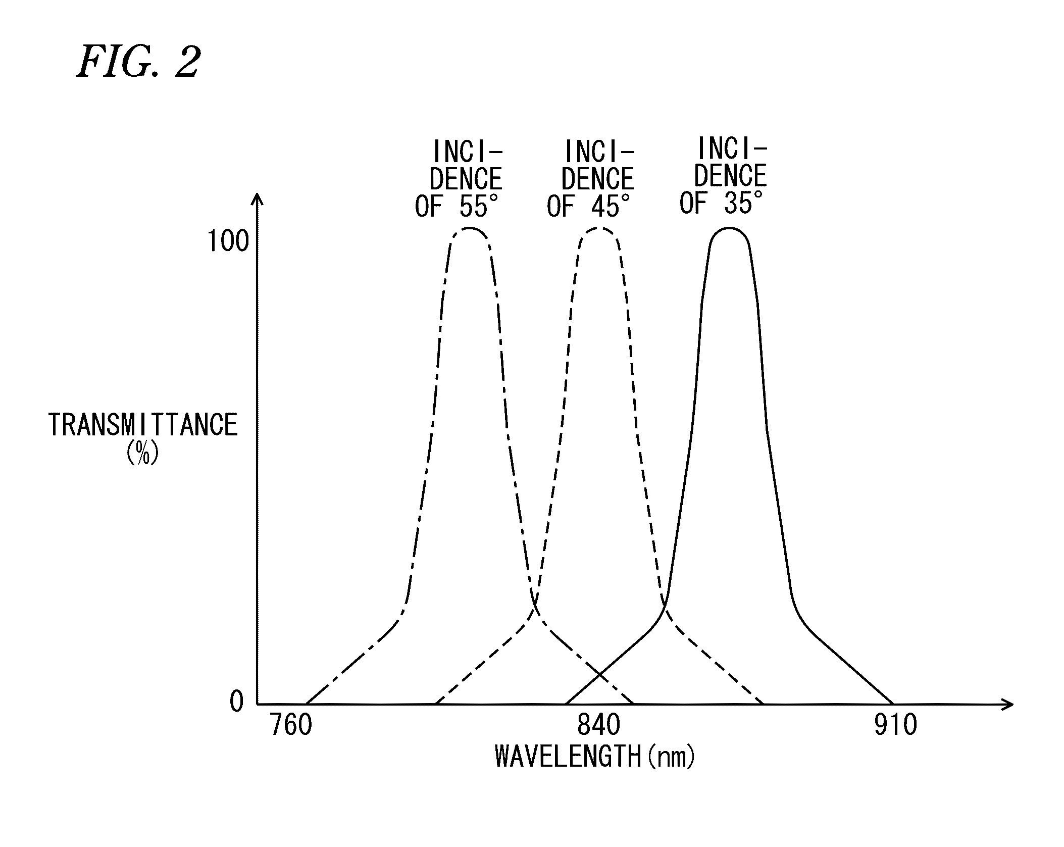
[0141]The light source unit 230 includes a light source 240 and a light source 250 with different wavelengths and optical axes, and is installed so that emitted light of each of the light sources is obliquely applied to a surface including a measurement region M of paper 500 from different positions. In the second embodiment, the light source 240 emits light of 820 nm and the light source 250 emits light o...
PUM
| Property | Measurement | Unit |
|---|---|---|
| wavelengths | aaaaa | aaaaa |
| wavelength | aaaaa | aaaaa |
| incidence angles | aaaaa | aaaaa |
Abstract
Description
Claims
Application Information
 - R&D
- Intellectual Property
- Life Sciences
- Materials
- Tech Scout
- Unparalleled Data Quality
- Higher Quality Content
- 60% Fewer Hallucinations
Browse by: Latest US Patents, China's latest patents, Technical Efficacy Thesaurus, Application Domain, Technology Topic, Popular Technical Reports.
© 2025 PatSnap. All rights reserved.Legal|Privacy policy|Modern Slavery Act Transparency Statement|Sitemap|About US| Contact US: help@patsnap.com


