
Branched shape optical isolator and optical apparatus, method and applications

a technology of optical isolators and optical components, applied in the field of optical devices, can solve the problems of difficult realization of similar components, noise problems, and the apparatus of lasers are not entirely without problems, and achieve the effects of efficient heat sinking, efficient coupling, and efficient heat sinking

Active Publication Date: 2016-09-13
UNIV OF CENT FLORIDA RES FOUND INC
View PDF14 Cites 5 Cited by
  • Summary
  • Abstract
  • Description
  • Claims
  • Application Information

AI Technical Summary

Benefits of technology

This solution reduces unwanted reflections and noise in laser apparatus by preferentially directing backscattered radiation away from the laser cavity and enhances heat dissipation, enabling high-power operation with low internal optical loss and efficient coupling to waveguides.

Problems solved by technology

While such laser apparatus and optical data communication systems are desirable within the optical communications fields, such laser apparatus are nonetheless not entirely without problems.
Lasers are particularly sensitive to unwanted optical signals or optical noise that enter their laser cavity and cause noise problems.
Although many laser apparatus and photonic components that use optical fibers also make use of optical isolators in the form of Faraday rotators, similar componentry has been difficult to realize in planar lightwave circuits or photonic integrated circuits (PICs) that use planar waveguides.
In particular, the Faraday rotator approach is difficult to realize using compatible processes with the fabrication of the PICs.
In addition, integrating lasers into planar lightwave or integrated photonic circuits can present additional difficulties in heat sinking and efficient optical coupling to a planar waveguide.

Method used


Image

  • Branched shape optical isolator and optical apparatus, method and applications
  • Branched shape optical isolator and optical apparatus, method and applications
  • Branched shape optical isolator and optical apparatus, method and applications

Examples


first embodiment

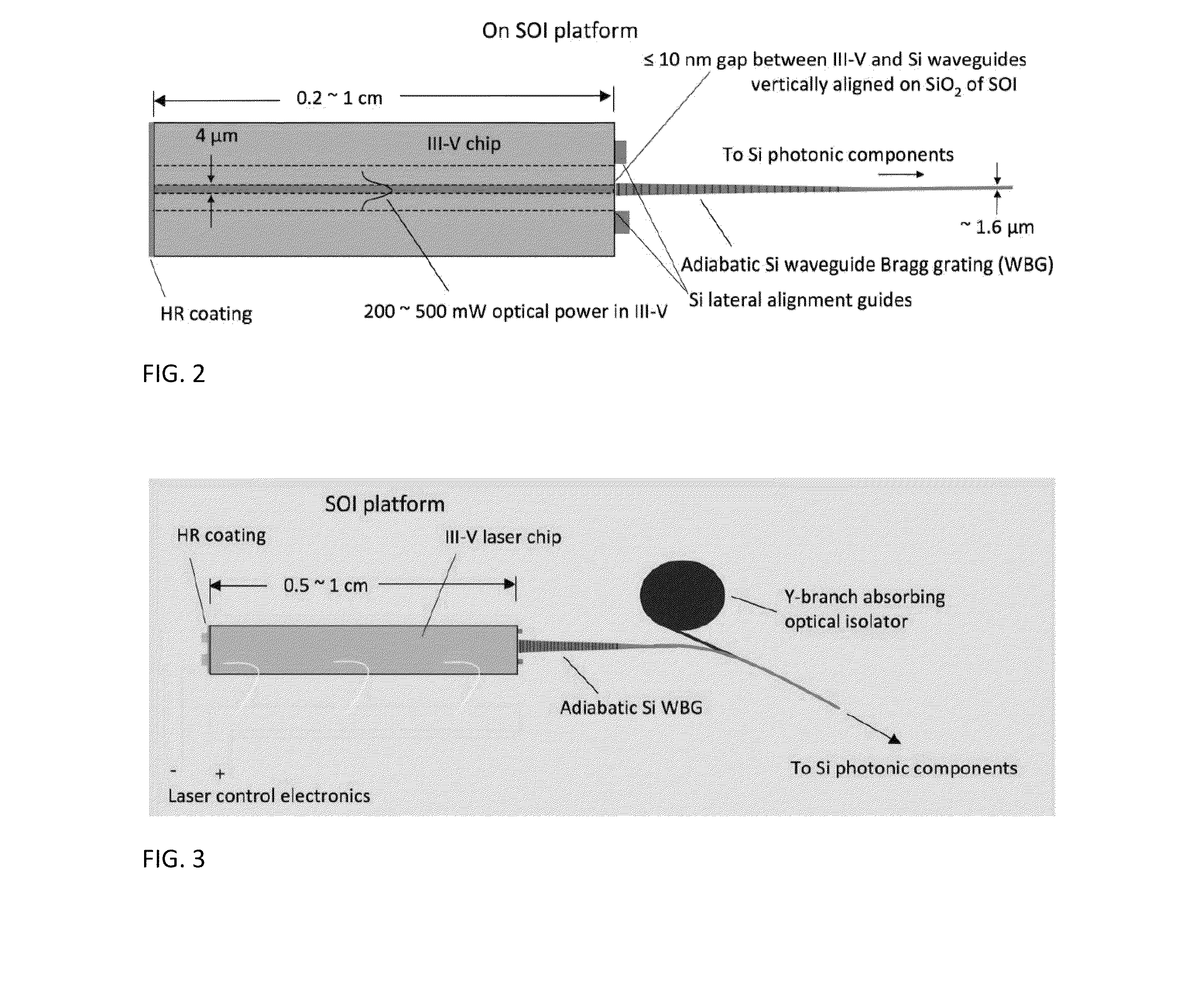
[0035]FIG. 12a and FIG. 12b show two schematic diagrams illustrating two embodiments of a branched optical isolator in accordance with the embodiments. In a first embodiment as illustrated in FIG. 12a, there is illustrated the branched optical isolator embodiment that includes an upper optically absorbing section and an upper optically transmitting waveguide section that are joined at a midpoint of the branched optical isolator and lead through the bottom optically transmitting waveguide section of the branched optical isolator to additional circuitry as indicated by the arrow at the bottom of the branched optical isolator. Within the schematic diagram of FIG. 12a, and although not illustrated, an optical chip (i.e., in particular a laser chip) is intended as attached to the distal left hand end of the optically transparent waveguide section. Within the schematic diagram of FIG. 12a, and as is illustrated, the optically absorbing section terminates in a nodal portion to which is tan...

second embodiment

[0040]Within the branched optical isolator in accordance with the embodiments as illustrated in FIG. 12b, there is added a gap interposed between the optically transparent upper waveguide section and the optically transparent lower waveguide section. The gap has a width from about 0.0001 to about 1 microns. The gap can provide greater isolation while also providing efficient coupling into the optical transmitting section.

[0041]FIG. 13 on the left shows a straight lossless waveguide with a confined mode propagating down the guide. The Poynting vector points along the normal to the guide giving the direction of energy flow. On the right is shown the propagation for the same guide filled partly with loss material. The result is that the Poynting vector is directed towards the lossy region. The reason is that the energy flow is into the loss region due to absorption, and this is shown by the tilt in the Poynting vector. If the direction were reversed the Poynting vector would again be p...


PUM


Abstract

A branched optical isolator includes, located over a substrate, at least two branches connected to a trunk at a junction location. At least one branch comprises an optical absorber material and at least one branch comprises an optical transmitter material. The optical isolator may be incorporated into an optical chip carrier such that: (1) an optical emitting portion of an optical chip integral to or attached to the optical chip carrier; and (2) a connection to the optical isolator, are butt connected with a gap less than 10 nanometers, and otherwise materials matched. The optical isolator provides for attenuated backscattered optical radiation into the optical chip.

Description

CROSS-REFERENCE TO RELATED APPLICATION[0001]This application is related to, and derives priority from, U.S. Provisional Patent Application Ser. No. 61 / 554,678, filed 2 Nov. 2011 and titled “Optical Isolator and Laser Apparatus, Method and Applications,” the content of which is incorporated herein fully by reference.BACKGROUND[0002]1. Field of the Invention[0003]The invention relates generally to optical apparatus (i.e., laser apparatus). More particularly the invention relates to integrated and optically isolated optical apparatus and semiconductor lasers.[0004]2. Description of the Related Art[0005]Laser apparatus are common apparatus with various applications in the optical data processing, storage and communication fields. While such laser apparatus and optical data communication systems are desirable within the optical communications fields, such laser apparatus are nonetheless not entirely without problems. Thus desirable within the optical data processing, storage and communic...

Claims


Application Information

Patent Timeline
Patent Type & Authority Patents(United States)
IPC IPC(8): G02B6/12B82Y20/00H01S5/00H01S5/022H01S5/14H01S5/34
CPCG02B6/12004B82Y20/00G02B2006/12061G02B2006/12121G02B2006/12126G02B2006/12157H01S5/0064H01S5/0224H01S5/141H01S5/3412H01S5/0234
Inventor DEPPE, DENNIS
Owner UNIV OF CENT FLORIDA RES FOUND INC
Learn More