
Method of fabricating a part out of CMC material

a technology of composite materials and manufacturing methods, applied in the direction of manufacturing tools, machines/engines, ceramic shaping apparatus, etc., can solve the problems of oxidizing atmosphere, short life of parts obtained by the second above-mentioned method, and relatively long densification process, so as to enhance the embrittlement-relief function, prevent or slow down the breakage of fibers, and enhance the crack deflection

Active Publication Date: 2016-09-13
SAFRAN CERAMICS SA
View PDF23 Cites 7 Cited by
  • Summary
  • Abstract
  • Description
  • Claims
  • Application Information

AI Technical Summary

Benefits of technology

The method provides improved crack resistance and extended lifespan at high temperatures, preserving the embrittlement-relief function and preventing interphase coating oxidation, enabling CMC materials to withstand temperatures above 800°C without the complexity of boron nitride formation and deposition.

Problems solved by technology

Nevertheless, CVI densification processes are relatively lengthy and expensive.
Nevertheless, in the presence of cracking, parts obtained by the second above-mentioned method present a lifetime that is short in an oxidizing atmosphere as from temperatures of about 800° C., because the BN material of the interphase coating oxidizes into B2O3 which, in the presence of moisture, forms a volatile oxide leading to BN material depletion, and thus to the embrittlement-relief function disappearing progressively.
Unfortunately, it is practically inevitable that CMC materials will be subjected to cracking because of the thermal cycling to which they are subjected in operation.
Furthermore, forming BN by CVI is complex and makes use of precursor gases of the NH3 and BCl3 or BF3 type, thus requiring an installation that is complex, in particular in order to process effluents on an industrial scale.
Furthermore, depositing a layer of SiC on the BN material of the interphase coating can be of limited effectiveness in protecting the coating while molten silicon is being infiltrated, since an SiC deposit obtained by CVI generally presents a columnar structure into which the molten silicon can become infiltrated.

Method used


Image

  • Method of fabricating a part out of CMC material
  • Method of fabricating a part out of CMC material

Examples


Embodiment Construction

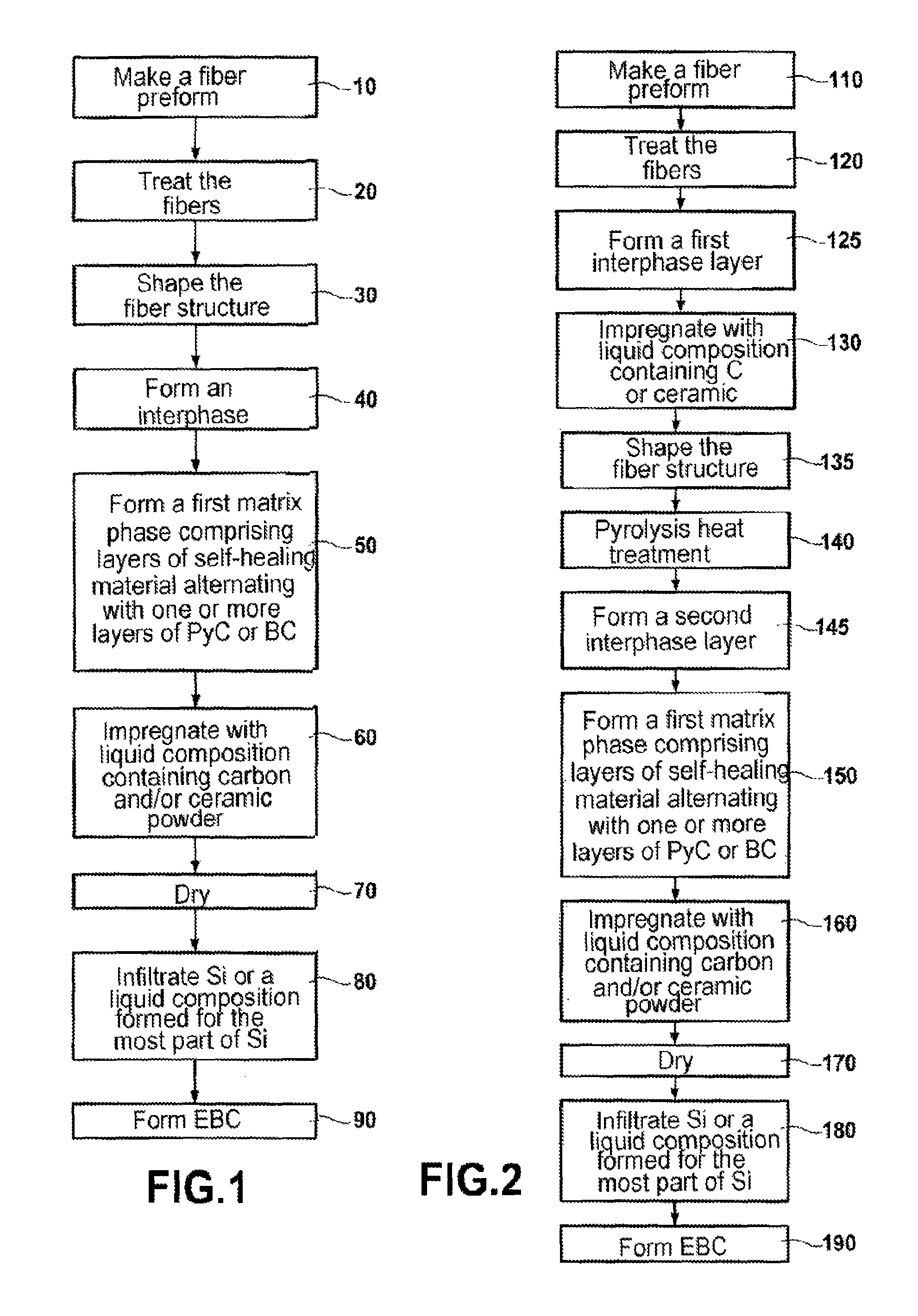
[0036]A first implementation of the invention is described with reference to FIG. 1.

[0037]A first step 10 consists in making a fiber structure from which a fiber preform is made having a shape close to the shape of the part that is to be fabricated. Such a fiber structure may be obtained by multilayer or three-dimensional weaving of yarns or tows. It is also possible to start from two-dimensional fiber textures such as woven fabric or sheets of yarns or tows in order to form plies that are then draped on a shape and possibly bonded together, e.g. by stitching or by implanting yarns.

[0038]The fibers constituting the fiber structure are preferably ceramic fibers, e.g. fibers made essentially of silicon carbide SiC (referred to below as SiC fibers), or of silicon nitride Si3N4. In particular, it is possible to use the SiC fibers sold under the name “Hi-Nicalon(S)” by the Japanese supplier Nippon Carbon. In a variant it is possible to use carbon fibers.

[0039]In known manner, with cerami...


PUM

PropertyMeasurementUnit
thicknessaaaaaaaaaa
thicknessaaaaaaaaaa
temperaturesaaaaaaaaaa

Abstract

Fabricating a composite material part comprises the steps of making a consolidated fiber preform, the fibers of the preform being carbon or ceramic fibers that are coated in an interphase formed by at least one layer of pyrolytic carbon (PyC) or of boron-doped carbon (BC). Obtaining a partially densified consolidated fiber preform, where partial densification comprises forming a first matrix phase on the interphase, the first matrix phase comprising a plurality of layers of self-healing material alternating with one or more layers of PyC or of BC. Continuing densification by dispersing carbon and / or ceramic powder within the partially densified consolidated preform and by infiltrating molten silicon or a liquid composition formed for the most part of silicon.

Description

BACKGROUND OF THE INVENTION[0001]The invention relates to making parts out of composite material having a matrix that is ceramic or at least partially ceramic, and referred to below as a CMC material.[0002]The field of application of the invention is making parts that are to be exposed in operation to high temperatures in an oxidizing atmosphere, and in particular in the fields of aviation and space, specifically parts for the hot portions of aviation turbine engines, it being understood that the invention may be applied in other fields, for example in the field of industrial gas turbines.[0003]CMC materials possess good thermostructural properties, i.e. strong mechanical properties that make them suitable for constituting structural parts, together with the ability to conserve those properties at high temperatures.[0004]The use of CMC materials instead of metal materials for parts that are exposed in operation to high temperatures has therefore been recommended, particularly since ...

Claims


Application Information

Patent Timeline
Patent Type & Authority Patents(United States)
IPC IPC(8): B28B11/00C04B35/628C04B35/573C04B41/85C04B35/80C04B41/50C04B41/00
CPCC04B41/85C04B35/573C04B35/62873C04B35/806C04B41/009C04B41/5024C04B35/565C04B35/584C04B2237/00F05D2300/6033C04B2235/422C04B2235/428C04B2235/5248C04B2235/5252C04B2235/614C04B2235/616C04B2235/72C04B2235/5244C04B35/80
Inventor BOUILLON, ERICPHILIPPE, ERICLAFOND, ANDRELAMOUROUX, FRANCK
Owner SAFRAN CERAMICS SA
Learn More