Carrier board structure

Active Publication Date: 2016-09-06
KINSUS INTERCONNECT TECH
View PDF3 Cites 8 Cited by
  • Summary
  • Abstract
  • Description
  • Claims
  • Application Information

AI Technical Summary

Benefits of technology

The invention provides a carrier board with flexible components that have fold lines on the connections between the middle and side regions. The fold lines have a groove shape that allows the side region to fold up or down without damaging the magnetic coils embedded in the flexible board. The carrier board also has upper and lower magnetic coils that enhance the magnetic induction effect with limited area. This improves workability and reliability in the subsequent processes for the carrier board.

Problems solved by technology

While such a rigid circuit board exhibits good mechanical strength, it is difficult to use in the actual application with limited area like mobile phones because it can not easily fold without damage.
Additional processes are thus needed and the problem of less preciseness for alignment of respective holes of the coils and the flexible boards often occurs.
As a result, the whole electrical performance of the carrier board is adversely affected due to misalignment or skew.

Method used


Image

  • Carrier board structure
  • Carrier board structure
  • Carrier board structure

Examples


Embodiment Construction

[0018]The present invention may be embodied in various forms and the details of the preferred embodiments of the present invention will be described in the subsequent content with reference to the accompanying drawings. The drawings (not to scale) show and depict only the preferred embodiments of the invention and shall not be considered as limitations to the scope of the present invention. Modifications of the shape of the present invention shall too be considered to be within the spirit of the present invention.

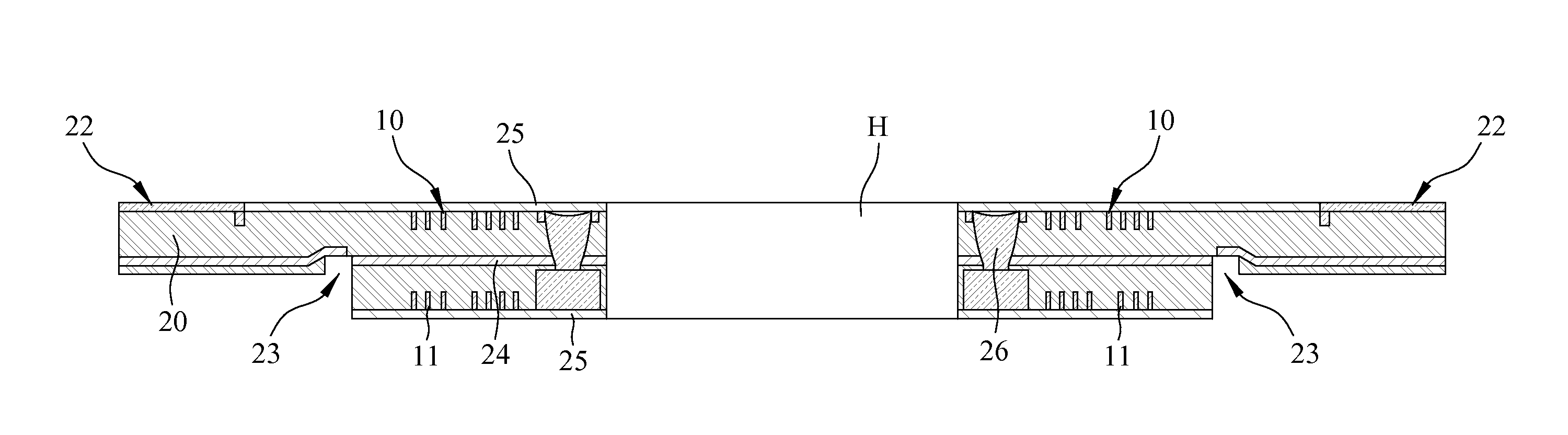
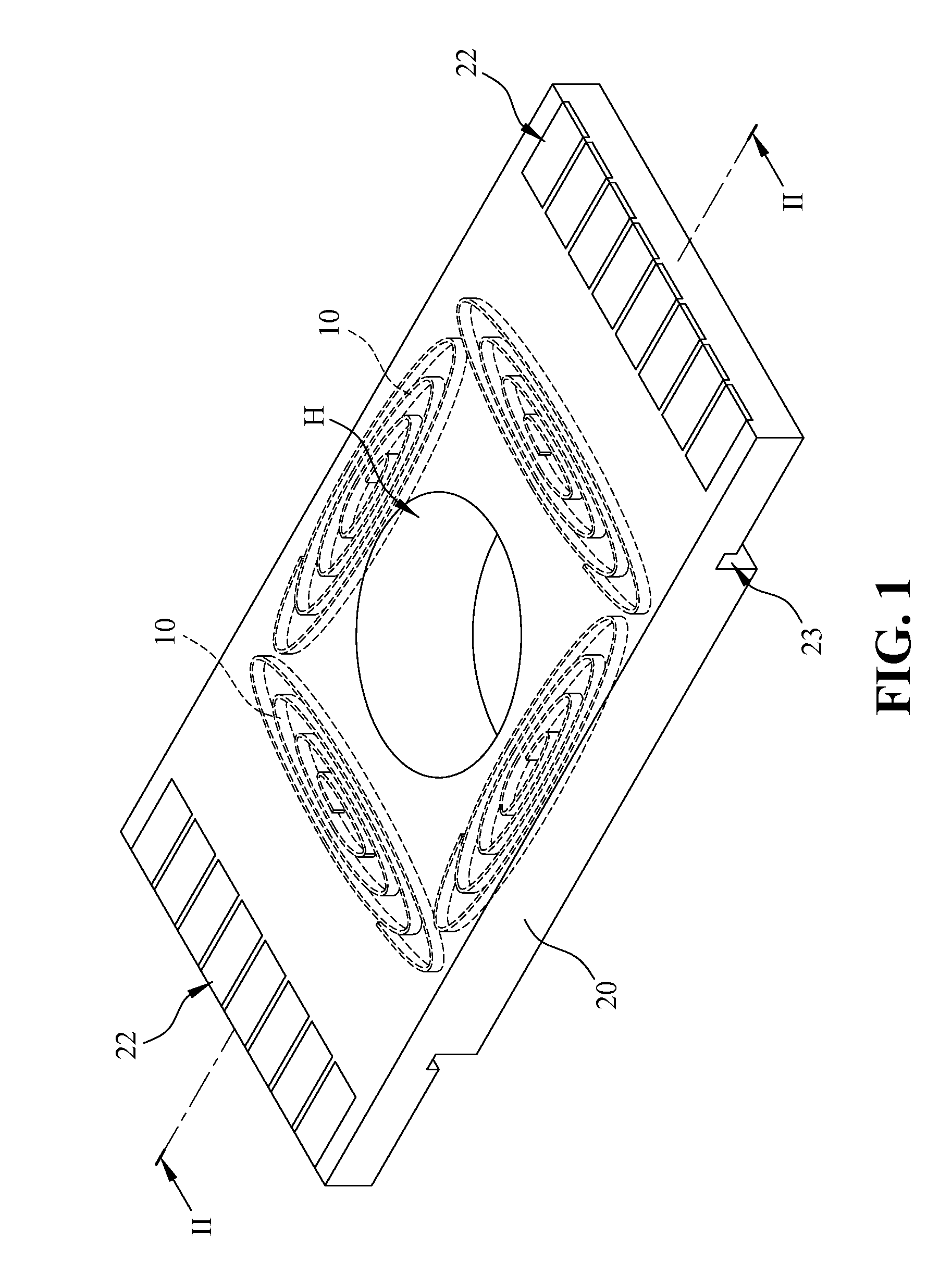
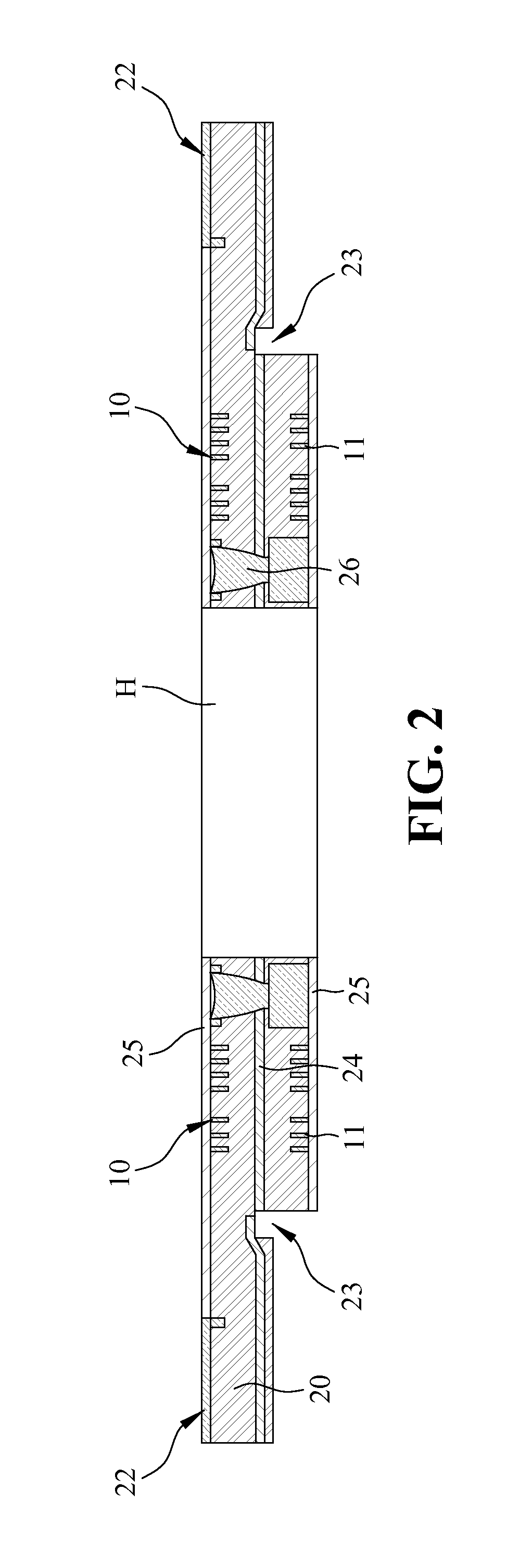
[0019]Please refer to FIGS. 1 and 2. FIG. 1 is a perspective view showing a carrier board structure according to the first embodiment of the present invention, and FIG. 2 is a cross sectional view showing the carrier board structure of the present invention in FIG. 1. As shown in FIGS. 1 and 2, the carrier board structure of the present invention is foldable and applicable to the field of magnetic induction, and generally comprises at least one upper magnetic coil 10, at le...


PUM


Abstract

A carrier board structure includes at least one upper magnetic coil, at least one lower magnetic coil, a flexible board, a dielectric layer, at least one connection pad and at least one gold finger. The flexible board has a middle region having a middle hole, and two side regions thinner than the middle region. A groove used as a fold line is provided on the lower surface of each side region bordering on the middle region. The upper and lower magnetic coils are configured in the flexible board and separated by the dielectric layer. The gold fingers are provided on the two side regions and connected to the upper magnetic coils. The upper and lower magnetic coils are around the middle hole and connected by the connection pads. The fold lines help the two side regions to fold without damage to the upper and lower magnetic coils.

Description

BACKGROUND OF THE INVENTION[0001]1. Field of the Invention[0002]The present invention generally relates to a carrier board structure, and more specifically to a carrier board structure having at least one magnetic coil and a flexible board provided in a carrier board so as to avoid the process of attaching the magnetic coil to the flexible board and increase preciseness of alignment as a hole being drilled through the coil and the flexible board.[0003]2. The Prior Arts[0004]In general, electrical appliances need rigid circuit boards to install and connect various electrical or electronic elements. One of the most commonly used material for the rigid circuit board is epoxy substrate because of excellent electrical insulation. While such a rigid circuit board exhibits good mechanical strength, it is difficult to use in the actual application with limited area like mobile phones because it can not easily fold without damage. Thus, the manufacturers successfully developed flexible circu...

Claims


Application Information

Patent Timeline
IPC IPC(8): H01F27/30H01F27/28H05K1/02H01F27/29H05K1/18H01F5/00
CPCH05K1/189H05K1/028H01F27/28H05K2201/1003H01F17/0013H05K1/118H05K1/165H05K2201/09036H05K2201/09063
Inventor LIN, TING-HAOCHANG, CHIAO-CHENGLIN, YI-NONG
Owner KINSUS INTERCONNECT TECH
Why Eureka
Try Eureka