
Light source module of lamp for vehicle

a technology of light source module and lamp, which is applied in the direction of fixed installation, lighting and heating apparatus, instruments, etc., can solve the problems of increased cost, poor light visibility, and low design flexibility, and achieves the effect of reducing the cost of installation

Active Publication Date: 2016-08-16
HYUNDAI MOTOR CO LTD
View PDF14 Cites 0 Cited by
  • Summary
  • Abstract
  • Description
  • Claims
  • Application Information

AI Technical Summary

Benefits of technology

The present invention provides a light source module for a vehicle that improves visibility without increasing the number of light sources and reduces the size and weight of the lamp, thereby achieving cost savings. The module includes a patterned film that creates a stereoscopic light-emission image when the LED light source is turned on, and a reflective film that improves visibility when the LED light source is not turned on. The module also includes a bezel image that makes the rear combination lamp look luxurious. The invention also includes a light diffusion preventing film that prevents direct output of light from the LED light source to the lens, and a reflective film that increases light efficiency by reflecting the light emitted from the LED light source and diffused to the back side of the lamp back to the optical pattern formed in the patterned film.

Problems solved by technology

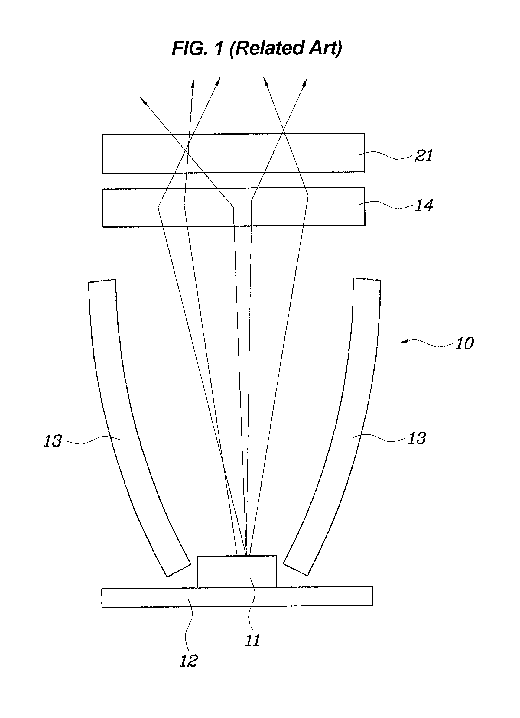
First, since the conventional light source module 10 is equipped with the reflecting plate 13 installed in front the LED light source 11, the entire optical system including the LED light source 11 and the outer lens 21 has a large size, leading to low flexibility in design, heavy weight, and increased cost.
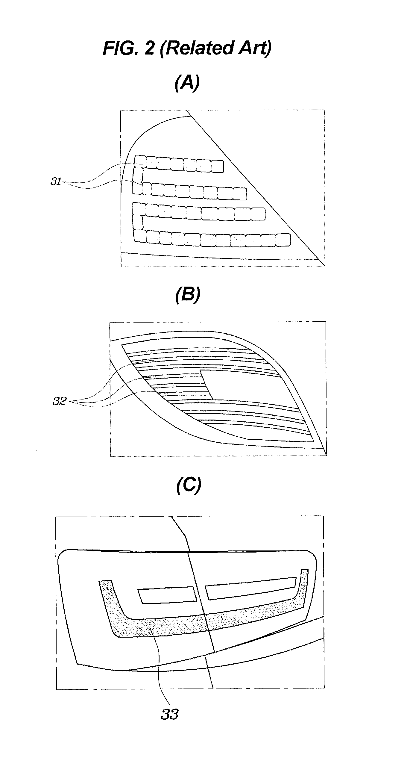
Second, since the conventional light source module 10 emits light by converting the light emitted from the LED light source 11 into a simple image such as point, line, and plane, its light is poorly visible.
When increasing the number of the LED light sources 11 to improve the poor visibility, the cost greatly increases.

Method used


Image

  • Light source module of lamp for vehicle
  • Light source module of lamp for vehicle
  • Light source module of lamp for vehicle

Examples


Embodiment Construction

[0044]Reference will now be made in detail to various embodiments of the present invention(s), examples of which are illustrated in the accompanying drawings and described below. While the invention(s) will be described in conjunction with exemplary embodiments, it will be understood that the present description is not intended to limit the invention(s) to those exemplary embodiments. On the contrary, the invention(s) is / are intended to cover not only the exemplary embodiments, but also various alternatives, modifications, equivalents and other embodiments, which may be included within the spirit and scope of the invention as defined by the appended claims.

[0045]Hereinbelow, preferred embodiments of the present invention will be described in detail with reference to the accompanying drawings.

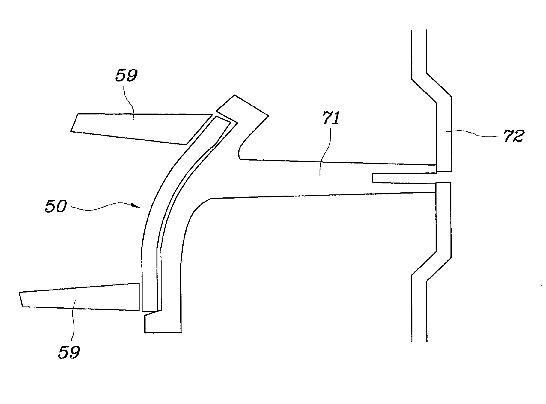
[0046]As illustrated in FIGS. 3 to 5, a rear combination lamp according to one embodiment of the present invention includes an LED light source 51, a PCB substrate 52, a patterned film 53, optic...


PUM


Abstract

Disclosed is a light source module for a vehicle. The light source module includes an LED light source, a PCB that controls supply of current to the LED light source, a patterned film disposed on the PCB and provided with an optical pattern which enables a stereoscopic light-emission image of a desired pattern to be formed when light from the LED light source is emitted thereto, and optical resin that is disposed on the patterned film and uniformly transmits the light from the LED light source to the entire range of the patterned film. The light source module improves visibility of the LED light source and makes a lamp using the light source module look luxurious by using a hidden effect of a deposited film even when the LED light source is not turned on.

Description

CROSS REFERENCE TO RELATED APPLICATION[0001]The present application claims priority to Korean Patent Application No. 10-2013-0158791 filed on Dec. 18, 2013, the entire contents of which is incorporated herein for all purposes by this reference.BACKGROUND OF THE INVENTION[0002]1. Field of the Invention[0003]The present invention relates to a light source module of a lamp for a vehicle, and more particularly to a light source module which makes up a rear combination lamp.[0004]2. Description of the Related Art[0005]The term “rear combination lamp” for a vehicle represents lamps mounted at the back of a vehicle, for example, including a back up lamp which is turned on when the transmission is shifted to reverse gear, a stop lamp which is turned on when a driver steps down a brake pedal, and a turn signal lamp.[0006]Recently, use of rear combination lamps using a Light Emitting Diode (LED) as a light source, which has longer life span and higher light efficiency than conventional light ...

Claims


Application Information

Patent Timeline
Patent Type & Authority Patents(United States)
IPC IPC(8): G02B27/22F21S8/10B60Q1/26
CPCF21S48/215F21S48/238F21S48/212G02B27/2221B60Q1/26F21V13/10F21Y2101/00F21S43/14F21S43/33F21W2103/00F21S43/195G02B30/40F21Y2105/10F21S43/235H01L33/52H01L33/60
Inventor YANG, JEONG GYU
Owner HYUNDAI MOTOR CO LTD
Learn More