
Instrument and method for detecting partial electric discharges in an electric apparatus

a technology of partial electric discharge and instrument, which is applied in the direction of instruments, testing circuits, resistance/reactance/impedence, etc., can solve the problems of not yet becoming a standard industrial tool for planning maintenance and/or substitution of high-voltage electrical components, detection and subsequent processing of partial discharges for diagnostic purposes, and substantially limited partial discharges, etc., to achieve simple and convenient use, the effect of optimizing the calculation resources

Active Publication Date: 2016-07-26
I S A ALTANOVA GRP SRL
View PDF17 Cites 0 Cited by
  • Summary
  • Abstract
  • Description
  • Claims
  • Application Information

AI Technical Summary

Benefits of technology

The invention provides an instrument and method for detecting partial electric discharges that optimizes computing resources and minimizes unwanted signals. It is also simple and convenient to use, even for non-specialist personnel. Additionally, it allows for focusing on signals related to specific discharge activities, preventing detection of all other signals.

Problems solved by technology

By their very nature, therefore, partial discharges are substantially limited in extent to a defect in the insulating system.
The detection and subsequent processing of partial discharges for diagnostic purposes, however, has not yet become a standard industrial tool for planning the maintenance and / or substitution of high-voltage electrical components on account of the difficulties encountered in interpreting the results of measurements.
As to the difficulties of interpreting the results of partial discharge measurements, these depend not only on the need to have experience and a specific case history but also on the fact that the measured data may be unreliable or insignificant.
In light of this, the problems that invalidate diagnostics based on the measurement of partial discharges are essentially of two kinds:during detection of the signals associated with the partial discharges, information essential for subsequent processing of the signals themselves for diagnostic purposes may be lost (loss of information might consist, for example, of failure to detect a pulse, or assigning to a certain partial discharge activity a signal from another source or relating to a different discharge activity);during such detection, noise may be superposed on the discharge signals or the signals from different sources may be superposed on each other, thus making it objectively difficult to interpret the results since it is impossible to perform significant statistical processes on data which is not uniform and / or not pertinent to the individual partial discharges to be processed.
Thus, with regard to the instrument used to detect the signals associated with the partial discharges, the problem is that of capturing very rapidly and efficiently electrical signals having a high frequency content, while maintaining the information content of the signals as much as possible.
The solution to the above mentioned problems is particularly difficult if we consider the need to detect the partial discharges and to process the state of the electric system in unattended manner or with the minimum of operator intervention (in some cases, such as online monitoring systems, there is no operator at all).
In practice, if unwanted signals (for example, signals associated with noise or discharge activities outside the measuring instrument) are superposed on the partial discharge activities to be detected, there is the risk that many of the discharge signals to be detected will remain undetected by the instrument, especially if the repetition rate of the unwanted signals is very high.
It does not, however, fully solve the above mentioned problems.
In effect, unwanted signals with particularly high repetition rates are sometimes superposed on the discharge activities to be monitored.
Indeed, in some cases, the unwanted signals have a waveform that is similar to (or at least easily-mistaken for) that of the signals to be detected.
Hence, the method of document WO2009 / 013639 does not allow real time filtering but aims to identify a strategy for locating the discharge sources based on the processing of data groups acquired on different sections of the electric apparatus being checked.

Method used


Image

  • Instrument and method for detecting partial electric discharges in an electric apparatus
  • Instrument and method for detecting partial electric discharges in an electric apparatus
  • Instrument and method for detecting partial electric discharges in an electric apparatus

Examples


Embodiment Construction

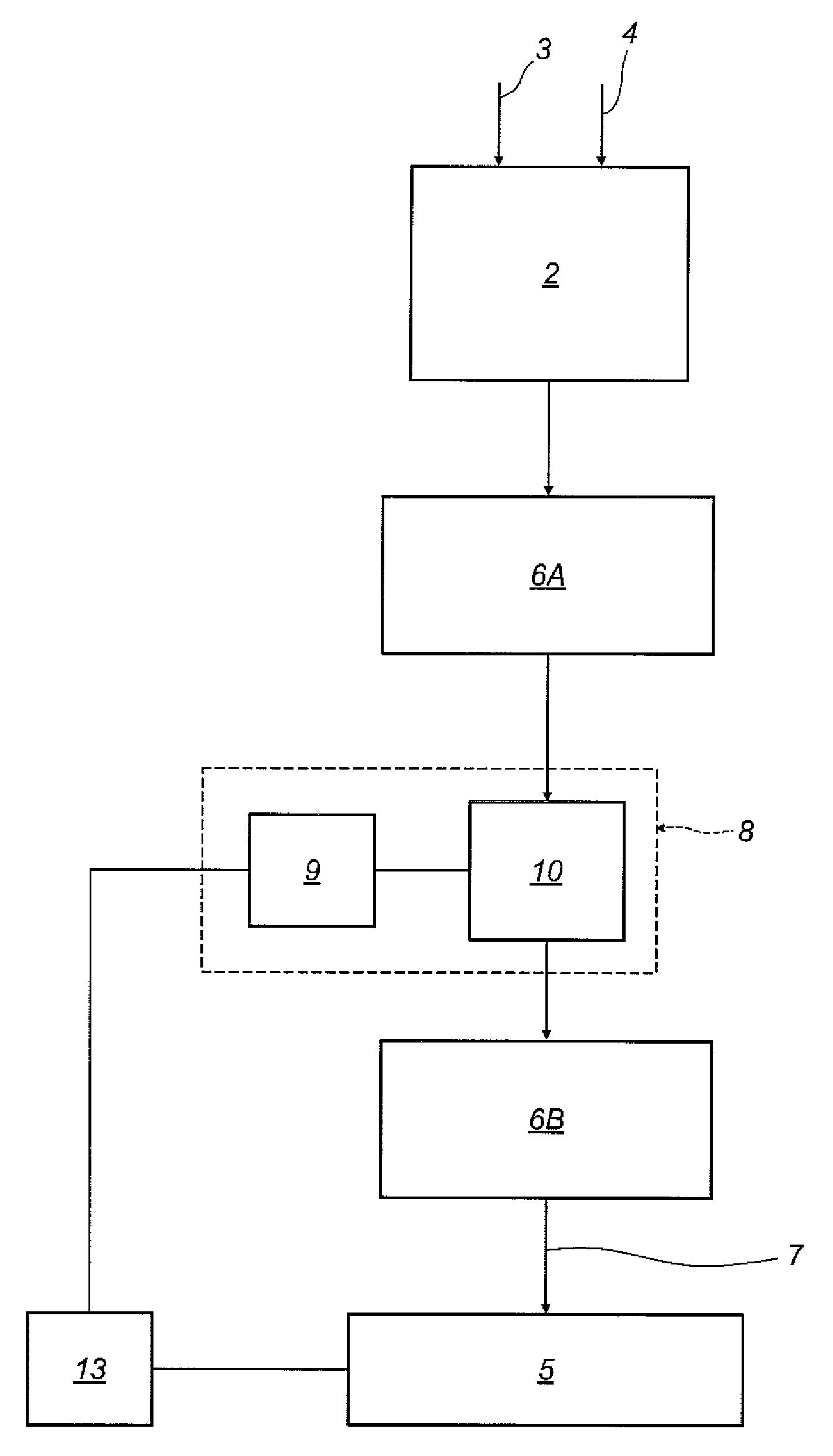
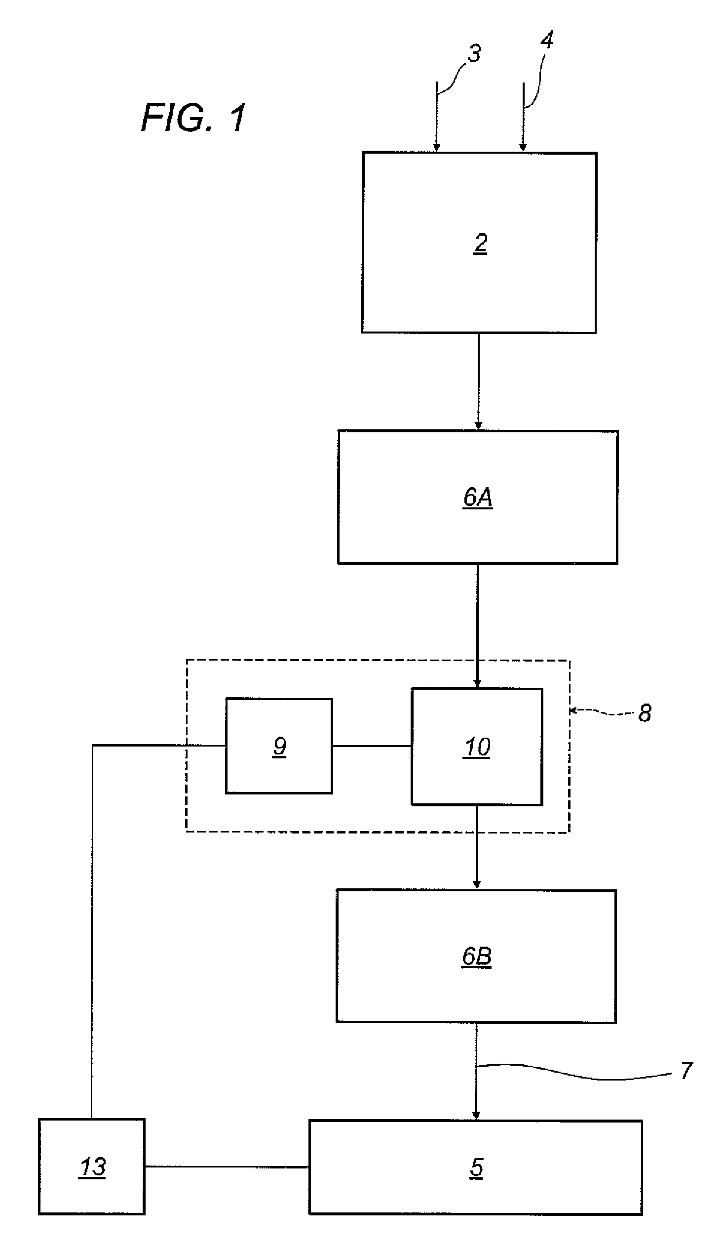
[0062]The numeral 1 in the accompanying drawings denotes an instrument for detecting partial electric discharges in an electric apparatus.

[0063]The electric apparatus is any electric apparatus comprising an insulating system to be diagnosed by measuring and analysing partial discharge activities taking place within the insulating system itself.

[0064]More specifically, during measurement of the partial discharges, it is assumed that the electrical apparatus (or rather, the insulating system of the electrical apparatus) is subjected to alternating current voltage (50 Hz in the example illustrated).

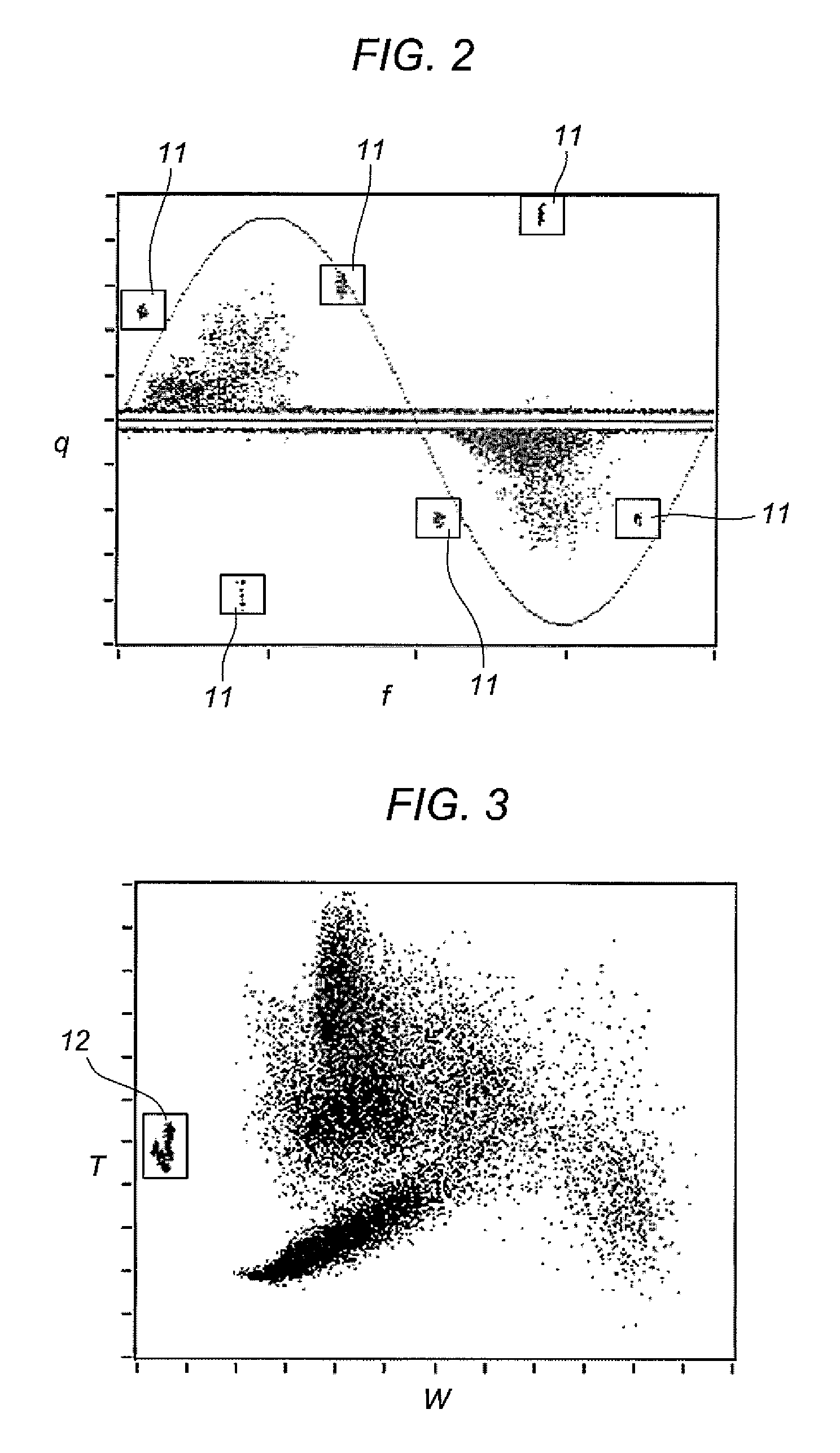
[0065]The fact that the electrical apparatus is subjected to alternating current voltage (typically sinusoidal) makes it possible to assign to each signal detected the value of a phase parameter given by the phase of the voltage applied to the electrical apparatus at the instant the signal is detected and hence representative of the value of the voltage applied to the electrical apparatus at...


PUM


Abstract

An instrument for detecting partial electric discharges includes: an input stage set up to receive a discharge signal representative of one or more partial discharge pulses and a sync signal representative of an alternating voltage applied to the electric apparatus; a data processing stage for receiving the discharge signal and the sync signal, and extracting substantially in real time for each pulse detected the value of an amplitude parameter, correlated with a pulse amplitude, and the value of a phase parameter, representative of the phase of the voltage applied to the electric apparatus concurrently with the pulse, and transferring to output a processed digital signal including the values extracted. The processing stage includes a filtering module set up to disable substantially in real time the transfer to output of the values of the parameters extracted for one or more pulses.

Description

TECHNICAL FIELD[0001]This invention relates to an instrument and a method for detecting partial electric discharges in an electric apparatus.BACKGROUND ART[0002]This invention relates to the technical field of diagnosing electrical systems (particularly high-voltage systems) by detecting and then processing partial electrical discharges.[0003]It should be noted that a partial discharge is an electric discharge limited to a portion of the insulation of an electrical system and does not therefore cause immediate failure of the system but its gradual degradation. By their very nature, therefore, partial discharges are substantially limited in extent to a defect in the insulating system.[0004]In light of this, diagnostic methods based on the detection and interpretation of partial discharges are among the most promising and widely studied in the context of scientific research since the study of partial discharges makes it possible to investigate the nature of defects in the insulating s...

Claims


Application Information

Patent Timeline
Patent Type & Authority Patents(United States)
IPC IPC(8): G06F19/00G01R31/12
CPCG01R31/1227G01R31/12G01R31/14
Inventor BETTIO, FABIANOMONTANARI, GIAN CARLO
Owner I S A ALTANOVA GRP SRL
Learn More