
Roofing shingle system and shingles for use therein

a technology for roofing shingles and shingles, which is applied in the direction of layered products, bituminous layered products, chemistry apparatuses and processes, etc., can solve the problems of leakage at the region of shingles, and achieve the effect of increasing the coverage of each shingle, increasing the utilization of materials, and increasing the resistance to infiltration

Active Publication Date: 2016-07-26
BMIC LLC
View PDF154 Cites 28 Cited by
  • Summary
  • Abstract
  • Description
  • Claims
  • Application Information

AI Technical Summary

Benefits of technology

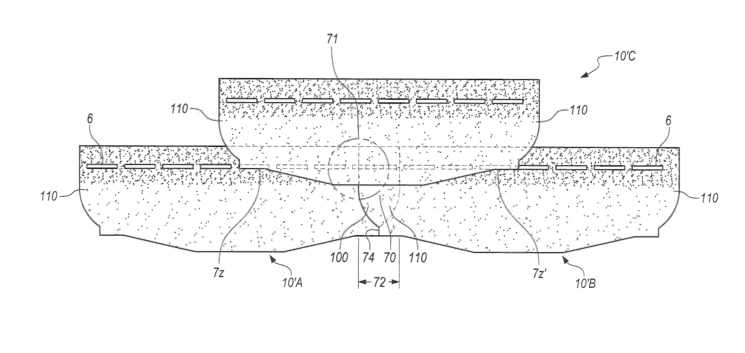
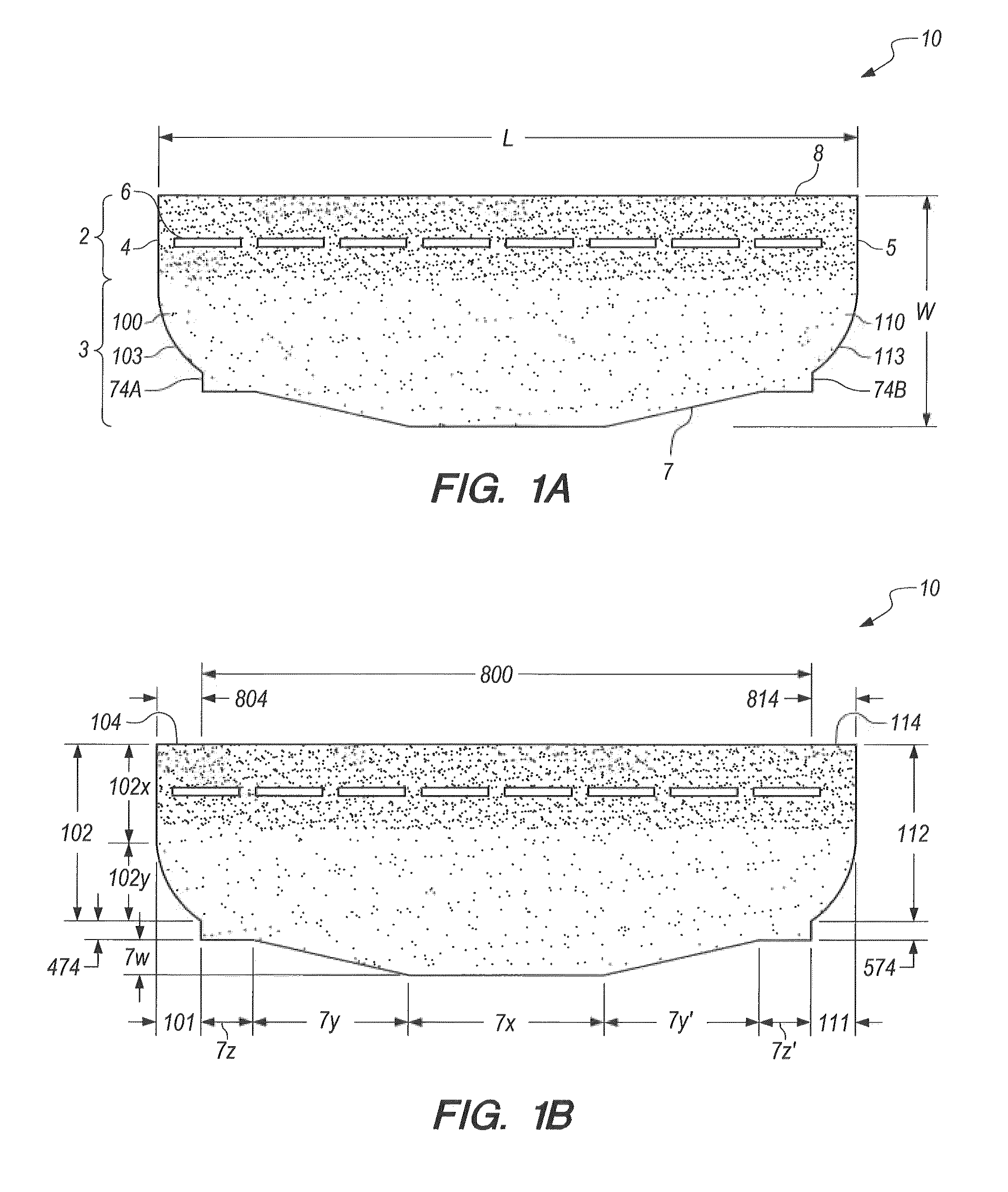
The present invention is a new roofing shingle that is designed to improve the utilization of materials needed to make the shingle and provide better resistance to water infiltration under high wind conditions. The shingle has a curved trailing edge projection that forms a side-lap region, which reduces wind impact and forms a connection with an adjacent shingle to prevent water infiltration. The shingle also has interlocking edges and a unique shape and dimension that increases the coverage of each shingle and allows for increased utilization of materials. Additionally, the shingle has a trailing edge projection with varying breath that dissipates wind impingements near the side-lap region and a leading edge projection that prevents water infiltration underneath the adjacent shingle. Overall, the invention provides an improved roofing system with these features.

Problems solved by technology

Thus, when the shingles are exposed to wet weather, it is possible that leakage can occur at the region where the shingles abut.
In some cases, prior art shingles may rely on redundant overlapping to ensure adequate water shedding performance, particularly in high wind or wind-driven rain conditions.

Method used


Image

  • Roofing shingle system and shingles for use therein
  • Roofing shingle system and shingles for use therein
  • Roofing shingle system and shingles for use therein

Examples


example

[0098]Shingles having length (l) and width (w) dimensions of 36″×12″, a reduced-width headlap and a trailing edge projection in accordance with the invention and a straight front longitudinal edge were prepared by following a typical reduced-headlap shingle production. A 4′×4′ test roof deck was constructed, wherein shingles of the invention were installed in accordance with the invention. The interlocking edge between adjacent shingles in the same course included a side-lap region having a maximum length of 6″ and a first abutment region and a second abutment region each having a height of 2″. The weather edge of the side-lap included a curved edge designed to provide wind dynamics for uplift reduction. A 4′×4′ control roof deck was constructed, wherein commercially available 3-tab shingles (Royal Sovereign shingle from GAF Corporation, Dallas, Tex.) were installed. Table 1 (below) lists the amount of shingle material needed per 100 ft2 based upon the deck construction calculation....


PUM

PropertyMeasurementUnit
heightaaaaaaaaaa
areaaaaaaaaaaa
areaaaaaaaaaaa

Abstract

A roofing system and roofing shingles for use therein are disclosed. The roofing system comprises a multiplicity of courses of roofing shingles having a headlap portion, a buttlap portion, a lateral leading edge, and a lateral trailing edge, wherein the headlap portion has a width that is less than a width of the buttlap portion defining a reduced-width headlap, wherein the lateral trailing edge of a shingle in a course partially overlaps and partially abuts the lateral leading edge of an adjacent previously installed shingle to form an interlocking edge between adjacent shingles in the course, and wherein the lateral edge includes a trailing edge projection having a weather edge, a rear edge, and a variable breadth that increases toward the rear edge of the trailing edge projection.

Description

RELATED APPLICATIONS[0001]This application is a continuation-in-part of U.S. Non-Provisional application Ser. No. 14 / 669,538, filed on Mar. 26, 2015, entitled “Roofing Shingle System and Shingles for Use Therein”, which is a continuation-in-part of U.S. Non-Provisional application Ser. No. 14 / 550,468, filed on Nov. 21, 2014, entitled “Roofing Shingle System and Shingles for Use Therein,” both of which are incorporated herein by reference in their entirety for all purposes within this application.FIELD OF THE INVENTION[0002]This invention relates to an improved roofing system and roofing shingles that may be utilized in the roofing system. In particular, the invention relates to roofing shingles featuring unique dimensions and a roofing system that utilizes the shingles.BACKGROUND OF THE INVENTION[0003]Rooting products are often divided into three broad groups: shingles, roll roofing, and underlayment. Shingles and roll roofing typically function as outer roof coverings designed to w...

Claims


Application Information

Patent Timeline
Patent Type & Authority Patents(United States)
IPC IPC(8): E04D1/12B32B11/02E04D1/26E04D1/28E04F13/08E04D1/20B32B11/12
CPCE04D1/12B32B11/02B32B11/12E04D1/20E04D1/26E04D1/28E04F13/0862E04F13/0864E04D1/125
Inventor LEITCH, OLANDUQUE, LUISSHIAO, MING-LIANGRAILKAR, SUDHIR
Owner BMIC LLC
Learn More