Photovoltaic junction for a solar cell

a photovoltaic junction and solar cell technology, applied in the field of photovoltaic junctions, can solve the problems of reducing the efficiency of the photovoltaic junction and the solar cell, poor material quality in the layer containing indium, etc., and achieves the effects of reducing the degree of shift, increasing nitrogen concentration, and long wavelengths

Active Publication Date: 2016-06-14
LUMENTUM OPERATIONS LLC
View PDF16 Cites 1 Cited by
  • Summary
  • Abstract
  • Description
  • Claims
  • Application Information

AI Technical Summary

Benefits of technology

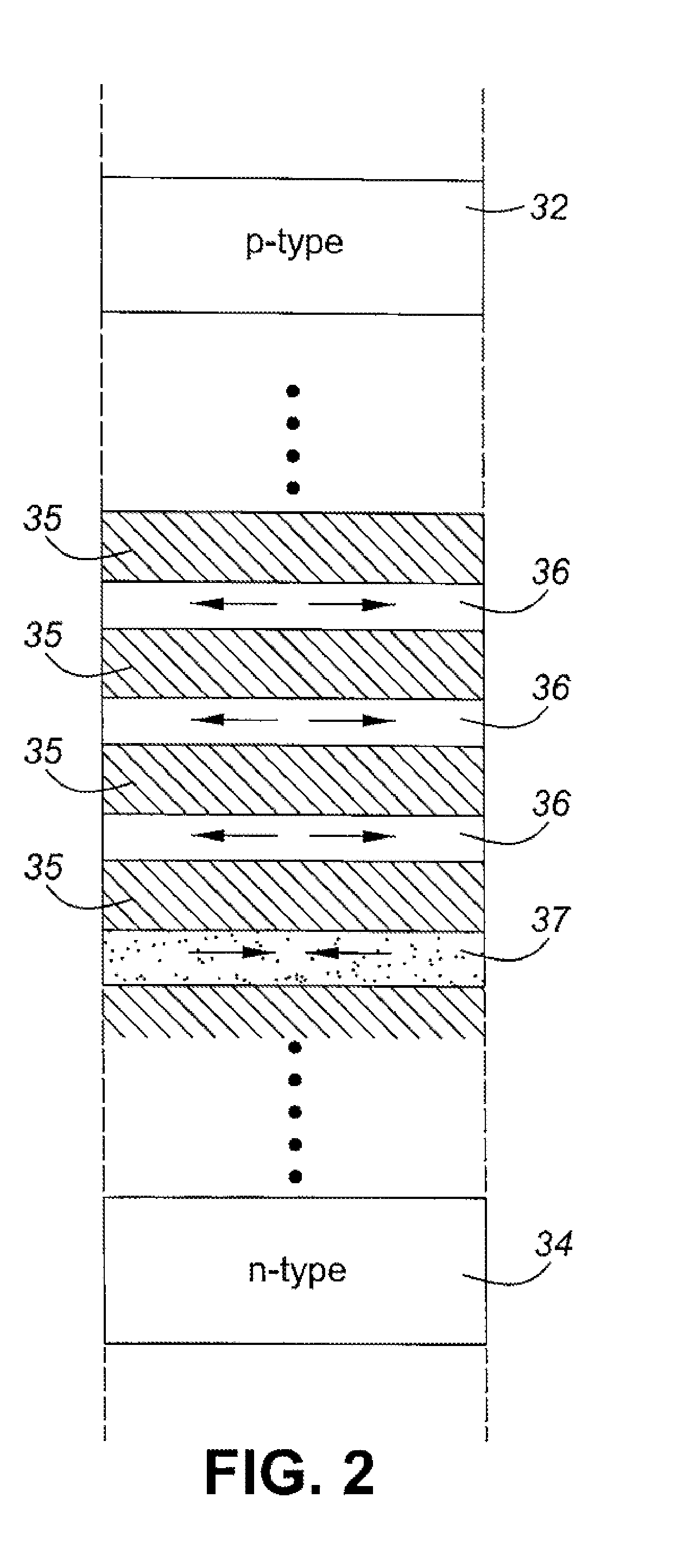
[0016]In prior art stress-balanced quantum well structures, either tensile or compressive stresses in the quantum wells are balanced by the opposite, i.e. either compressive or tensile stresses in the barriers. An advantage of the present invention, in which two types of wells with opposite stress types is used, is that the maximum stress differential between wells and barriers is much reduced. This is particularly important when larger lattice mismatches between the quantum well materials and the actual lattice size are needed, for example to achieve extensions to longer wavelengths of the absorption edge of a photovoltaic junction of a solar cell. In the prior art structures, local breakdown of the lattice coherence can be amplified by the strain differential at the interface between a quantum well and a barrier and trigger a local transition from 2D growth to 3D growth which rapidly propagates both laterally and along the growth direction with the formation of extended regions of highly damaged material, and the invention helps to reduce any such effects by reducing the strain differentials between layers.
[0017]In most prior art stress-balanced quantum well structures for solar cells, the quantum wells are under compressive strain, and the combined effects of this compressive strain and quantum confinement act to substantially shift the absorption edge to shorter wavelengths, reducing the degree of the shift to longer wavelengths which the quantum wells are intended to effect. An advantage of the invention, in which wells of a first type are under tensile strain, is to contribute to the shift to longer wavelengths of the absorption edge, and this effect increases with increasing nitrogen concentration in the wells of the first type where these are formed of a dilute nitride III-V material such as GaAsN.
[0018]In particular, the invention provides a photovoltaic junction, for example for a solar cell, typically grown monolithically using an epitaxial process. The photovoltaic junction comprises: first and second oppositely doped semiconductor regions; and an intrinsic region disposed between the doped regions, the intrinsic region comprising quantum wells of first and second types and barriers separating each of the quantum wells. The quantum wells of the first type are formed of one or more materials having a lattice constant less than the actual lattice size of the intrinsic region, or of the photovoltaic junction, or of the oppositely doped semiconductor regions, and the quantum wells of the second type being formed of one or more materials having a lattice constant greater than the actual lattice size of the intrinsic region, or of the photovoltaic junction or of the oppositely doped semiconductor regions.
[0019]The photovoltaic junction may also be improved by the provision of further doped semiconductor regions with either a higher doping or a higher bandgap, or both, than a doping and a bandgap of the doped semiconductor regions, forming layers known as ‘window’ or ‘front-surface field’ at the front side of the junction and / or a ‘back-surface field’ at the rear side of the junction. These additional doped semiconductor regions put in as cladding on the semiconductor regions, outside of the doped semiconductor regions, serve to improve the photocurrent collection efficiency in the doped semiconductor regions if photons are absorbed in those regions during operation.
[0020]A further advantage that may be gained from a photovoltaic junction of the invention would be the inclusion of a mirror, or semiconductor mirror (such as a Bragg reflector) formed of alternate layers of semiconductor material of differing refractive indices n1 and n2 respectively. The Bragg reflector can be placed adjacent to and outside of the doped semiconductor regions, preferably at a back side of the photovoltaic junction (that is, closer to the substrate than the junction). An advantage can be gained from designing the Bragg reflector so as the uppermost layer of the Bragg reflector, closest to the doped semiconductor regions, also acts as the ‘back-surface field’ region of the photovoltaic junction (an electronic effect), which reduces the amount of semiconductor material required in such a design and also serves to increase the absorption of the MQW region, should photons pass through unabsorbed, they can be reflected and a second possibility of absorption then exists for those photons (a photonic effect). A further advantage may also be gained by designing the lowermost layer of the Bragg reflector, such that it forms one side of the heavily doped tunnel junction which may be required to electrically connect successive junctions within a multiple junction stack. A tunnel junction can also be disposed at a top layer of the Bragg reflector, the closest to the doped semiconductor region.
[0021]Where the term lattice constant is used herein for a particular material it is defined herein to refer to the lattice spacing which the material would naturally adopt in the appropriate conditions without either compressive or tensile stress being exerted by adjacent monolithic materials of different lattice constant. The term lattice size, or actual lattice size is defined herein to refer to the lattice spacing which the material adopts under the influence of adjacent monolithic materials which may have different lattice constants or actual lattice sizes.

Problems solved by technology

In some epitaxial growth conditions, nitrogen may tend to enhance indium segregation effects, leading to poor material quality in layers containing indium, and therefore reduced efficiency of the photovoltaic junction and solar cell.

Method used


Image

  • Photovoltaic junction for a solar cell
  • Photovoltaic junction for a solar cell
  • Photovoltaic junction for a solar cell

Examples


Embodiment Construction

[0056]Referring now to FIG. 1, epitaxially grown layers of a solar cell according to a first embodiment of the invention are shown schematically in cross section. Not all layers are necessarily shown in the figure, and the layer thicknesses are not intended to be to scale. Broadly, the cell comprises a substrate 10 on which are formed one or more photovoltaic junctions. In this example, three photovoltaic junctions 12, 14, 16 are shown, but any suitable number may be used as required. The photovoltaic junctions are coupled using tunnel junctions 18, so that a common photocurrent passes through all of the junctions, for collection using electrodes 20 typically disposed beneath the substrate 10 to and on top of a window layer 22 overlying the uppermost photovoltaic junction 16. The photovoltaic junctions and other semiconductor layer structures are formed on the substrate using an epitaxial process such as chemical vapour deposition, to form a monolithic structure.

[0057]The substrate ...


PUM


Abstract

A photovoltaic junction for a solar cell is provided. The photovoltaic junction has an intrinsic region comprising a multiple quantum well stack formed from a series of quantum wells separated by barriers, in which the tensile stress in some of the quantum wells is partly or completely balanced by compressive stress in the others of the quantum wells. The overall elastostatic equilibrium of the multiple quantum well stack may be ensured by engineering the structural and optical properties of the quantum wells only, with the barriers having the same lattice constant as the materials used in the oppositely doped semiconductor regions of the junction, or equivalently as the actual lattice size of the junction or intrinsic region, or the bulk or effective lattice size of the substrate. Alternatively, the barriers may contribute to the stress balance.

Description

CROSS-REFERENCE TO RELATED APPLICATIONS[0001]This application is the national stage entry of International Appl. No. PCT / IB2011 / 002036, filed Aug. 31, 2011, which claims priority to Great Britain Patent Application No. 1014606.6, filed Sep. 2, 2010, each of which are incorporated herein by reference for all purposes.[0002]The present invention relates to a photovoltaic junction, for example for use in a solar cell, and in particular, to such a photovoltaic junction in which the intrinsic region contains a plurality of quantum wells formed of one or more materials having a lattice constant different to the actual lattice size of the junction.[0003]In particular, but not exclusively, the invention may be used in III-V semiconductor based concentrator solar cells, for example in such cells having multiple photovoltaic junctions grown monolithically in tandem based on a GaAs, SiGe or Ge substrate or lattice size.INTRODUCTION[0004]A photovoltaic cell usually comprises two or more layers ...

Claims


Application Information

Patent Timeline
Patent Type & Authority Patents(United States)
IPC IPC(8): H01L31/052H01L31/18H01L31/0304H01L31/0352H01L31/075B82Y20/00
CPCH01L31/035236B82Y20/00H01L31/03048H01L31/075H01L31/18H01L31/1848Y02E10/544Y02E10/548H01L27/142H01L31/0304
Inventor MAZZER, MASSIMOTIBBITS, THOMASBROWNE, BEN
Owner LUMENTUM OPERATIONS LLC
Why Eureka
Try Eureka