
Processing of time-of-flight signals

a technology of time-of-flight and time-of-flight, which is applied in the field of processing of time-of-flight (tof) signals, can solve the problems of affecting tof systems, distances to be erroneously determined, and major drawbacks of conventional tof camera systems

Active Publication Date: 2016-04-26
SOFTKINETIC SENSORS
View PDF2 Cites 14 Cited by
  • Summary
  • Abstract
  • Description
  • Claims
  • Application Information

AI Technical Summary

Benefits of technology

[0017]An advantage of the present invention is that the de-aliasing of TOF signals can be carried out in an efficient way. Aspects of embodiments of the present invention are:[0018]a) using two correlation processes, a first one for determining a distance or depth value and a second one for determining if there is aliasing present in the first correlation. These two processes can be made independent of each other.[0019]b) The first correlation of a) above can be given a higher priority than the second correlation, e.g. the computational effort for the first correlation can be higher for the first than for the second and / or the integration time for signals in the first correlation can be longer than for the second.[0020]c) Whereas one correlation process is used to obtain depth or distance information, two methods or processes can be used to determine if there is alisaing. The first of these processes preferably reduces the number of possible aliased values and the second process then focuses on or reduces the number of possible aliased values down to one or close to one, e.g. by a process of elimination.[0021]d) Adjudication processes, i.e. as to whether there is aliasing or not are preferably based on simple arithmetic, e.g. greater than or less than determinations.
[0018]a) using two correlation processes, a first one for determining a distance or depth value and a second one for determining if there is aliasing present in the first correlation. These two processes can be made independent of each other.
[0019]b) The first correlation of a) above can be given a higher priority than the second correlation, e.g. the computational effort for the first correlation can be higher for the first than for the second and / or the integration time for signals in the first correlation can be longer than for the second.
[0020]c) Whereas one correlation process is used to obtain depth or distance information, two methods or processes can be used to determine if there is alisaing. The first of these processes preferably reduces the number of possible aliased values and the second process then focuses on or reduces the number of possible aliased values down to one or close to one, e.g. by a process of elimination.
[0021]d) Adjudication processes, i.e. as to whether there is aliasing or not are preferably based on simple arithmetic, e.g. greater than or less than determinations.
[0022]In accordance with a first aspect of the present invention, there is provided a method of determining the presence of aliasing or avoiding aliasing within certain limits in correlation measurements in a time-of-flight system having an imaging sensor and being for use with an illumination unit, the illumination unit being adapted to illuminate a scene with modulated light, the system being adapted to obtain correlation measurements by applying a correlation signal to modulated light reflected from the scene,the method comprising:

Problems solved by technology

However, when using pulses, the pulse width of each light pulse determines the camera range, and, for example, for a pulse width of 50 ns, the range is limited to 7.5 m. As a consequence, the illumination of the scene becomes critical to the operation of a TOF camera system, and the requirements for illumination units necessitate the use of specialised light sources, such as, light emitting diodes (LEDs) or lasers, to generate such short light pulses.
The presence of background light may cause distances to be erroneously determined as the pixels receive additional light not reflected from objects within the scene.
Whilst it may be relatively easy to extract the distance information from the output of the imaging sensor for an object in a scene, TOF systems suffer from the impact of background light as discussed above; interference if more than one TOF camera system is operating with overlapping fields of view of the scene; and multiple reflections.
This is a major drawback of conventional TOF camera systems.
In TOF systems aliasing results in ambiguity as to the distance between the light source and object from the might is reflected.
Currently, a limited number of techniques exist to solve this problem of TOF aliasing to enable the TOF camera system to provide a non-ambiguous or unambiguous distance of sufficiently long an interval for the particular application in which the TOF camera system is implemented.
These techniques, however, have a number of known limitations as they tend to be quite complex to implement, require intensive computations, are not robust or cause bandwidth overheads in the data transport, or lead to a decrease of depth accuracy or general camera performance.

Method used


Image

  • Processing of time-of-flight signals
  • Processing of time-of-flight signals
  • Processing of time-of-flight signals

Examples


first embodiment

[0119]In accordance with the present invention, one extra measurement is made at a lower second frequency with the standard TOF technique described above. This measurement can, for example, be taken at a second frequency HALF, that is, half the first or BF. In that case, the system is able to discern k is even from k is odd, using the following relationships:

If QHALF>0→TOF measurement with k is even

If QHALF<0→TOF measurement with k is odd

[0120]Thus, only checking the sign of one measurement allows to reduce possible values for k to be either odd or even. Thus the unambiguous distance is increased a factor of 2, thereby reducing the reflectivity limit a factor of 4.

[0121]However, due to noise in this measurement, for example, when QHALF is very close to 0, the measurement can mistakenly be interpreted wrongly.

[0122]Alternatively, the IHALF measurements can also be used using the same relationships as above with the same issues of noise in the measurement.

[0123]To improve this, one co...

second embodiment

[0151]It has been found, however, that when increasing the modulation frequency which is beneficial for the performance of the TOF camera system, extending the maximum range of the system by four times may not be adequate. If a first frequency BF of 100 MHz is used having a natural non-ambiguity or unambiguous distance of 1.5 m, using second frequencies that are QUARTER frequencies as described with reference to the invention above, the non-ambiguity or unambiguous distance is now 6 m. If, however, due to the size of the region in which the TOF camera system is to operate limiting distance measurements to 3 m, the reflectivity limit becomes in first order 25% which makes distance determination for objects of lower reflectivity very difficult. Moreover, for systems where de-aliasing at a distance greater that 6 m is required, second frequencies that are QUARTER frequencies are therefore not sufficient.

[0152]As described above, second frequencies that are EIGHTH frequencies can be use...


PUM


Abstract

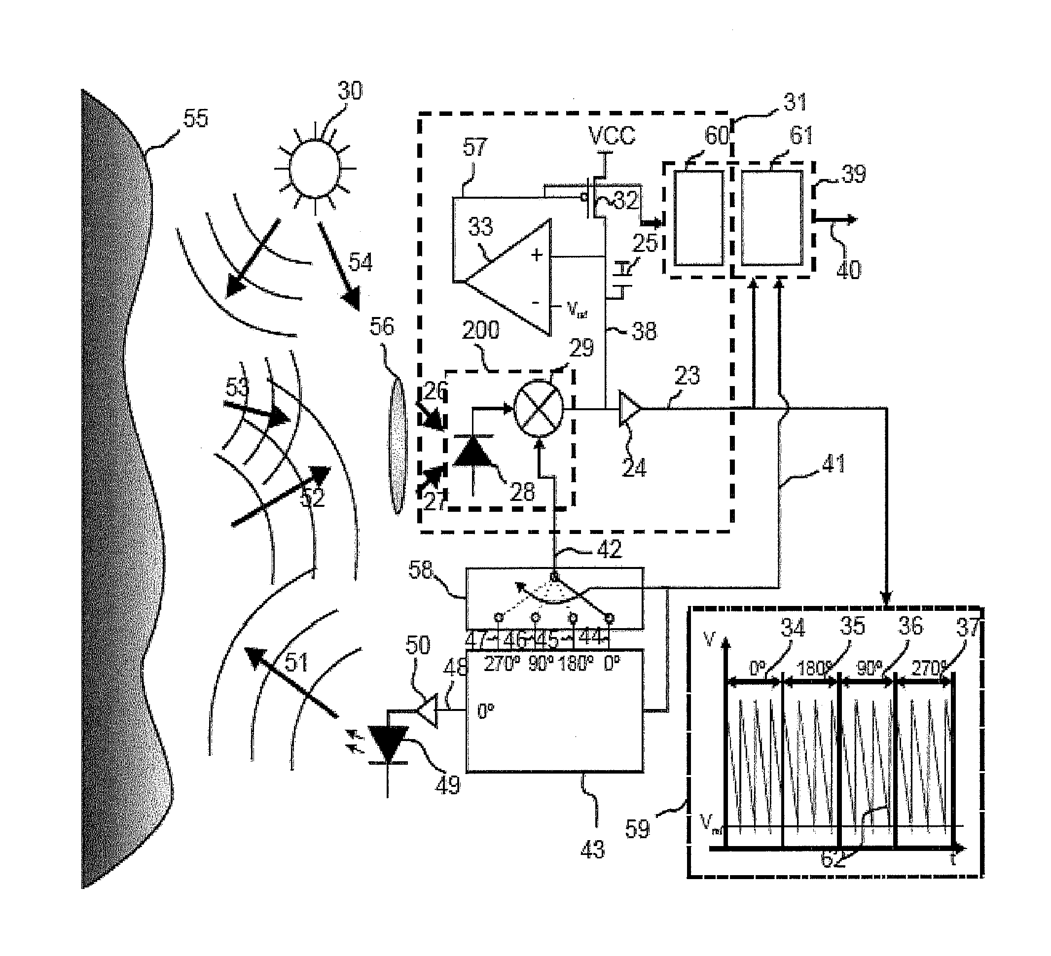
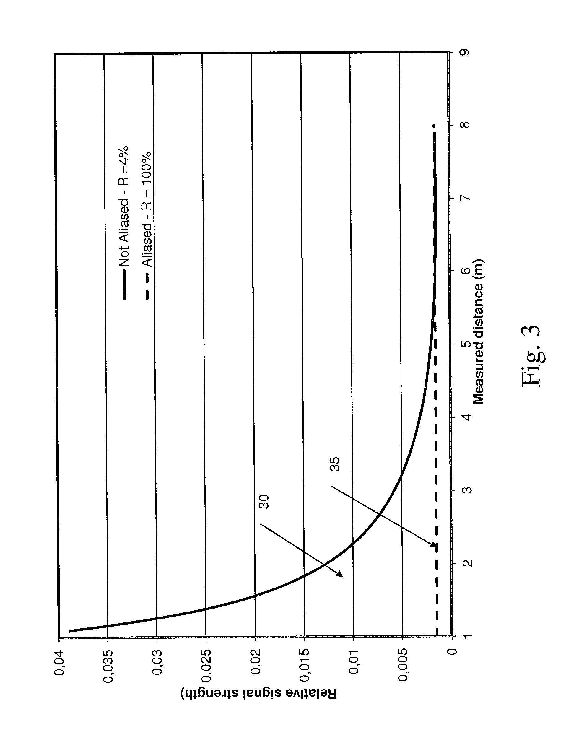
Described herein is a method and sensor of processing time-of-flight (TOF) signals in a TOF camera system including an illumination unit and an imaging sensor. The method comprises illuminating the scene with light at a first frequency, detecting reflected light from at least one object in the scene at the first frequency, and determining a phase measurement using I and Q values. In addition, the scene is illuminated with light at a second frequency, the second frequency being 2−n of the first frequency where n=1, 2, . . . , etc., and the signs of I and Q values for both the first and second frequencies is used to determine the presence of aliasing in the phase measurement so that it can be corrected. The phase measurement is then corrected for aliasing and the effective range of the TOF camera system is extended by multiples of 2n. In addition, relative signal strength needs to be considered in accordance with the reflectivity of objects within the scene. For a reflectivity of 4% and no aliasing, the ability to detect an object decreases with distance (30). For an aliased phase measurement for an object with a reflectivity of 100%, the ability to detect the object is substantially constant (35).

Description

CROSS-REFERENCE TO RELATED APPLICATIONS[0001]This application is a §371 national stage entry of International Application No. PCT / EP2013 / 050407, filed Jan. 10, 2013, which claims priority to European Patent Application No. 12150687.7 filed Jan. 10, 2012, the entire contents of which are incorporated herein by reference.FIELD OF THE INVENTION[0002]The present invention relates to improvements in or relating to the processing of time-of-flight (TOF) signals, and is more particularly concerned with de-aliasing of such time-of-flight signals. In particular the present invention relates to TOF sensors, cameras, etc. including de-aliasing of time-of-flight signalsBACKGROUND TO THE INVENTION[0003]Time-of-flight (TOF) camera systems are known for providing information concerning the distance to an object by analysis of the Time of Flight from a light source to the object and back. One particular application is a camera capable of capturing a three-dimensional (3-D) image of a scene, that is...

Claims


Application Information

Patent Timeline
Patent Type & Authority Patents(United States)
IPC IPC(8): H04N5/357G01S17/89G01S7/486G01S7/4865G01S17/894
CPCG01S17/89G01S7/4865H04N5/357G01S17/894G01S17/02H04N25/60
Inventor VAN NIEUWENHOVE, DANIELVAN DEN HAUWE, TOMASGROOTJANS, REIMERVAN DER TEMPEL, WARD
Owner SOFTKINETIC SENSORS
Learn More