
Method and system for protection switching in ethernet passive optical networks

a technology of protection switching and optical network, applied in the field of protection switching in ethernet passive optical network, can solve the problems of increasing access network capacity, unable to match the increase in backbone network capacity, and limited bandwidth offered by current access network, and achieve the effect of reducing service disruption tim

Active Publication Date: 2016-04-19
AVAGO TECH INT SALES PTE LTD
View PDF12 Cites 8 Cited by
  • Summary
  • Abstract
  • Description
  • Claims
  • Application Information

AI Technical Summary

Benefits of technology

The patent text describes a system that helps protect a network in a way that reduces service disruption time. It does this by detecting failures and automatically switching to redundant components. The system preserves existing configurations and helps the standby components recover network operation. This can be done by configuring the redundant components with the saved configurations. Overall, the system reduces downtime and makes the network more reliable.

Problems solved by technology

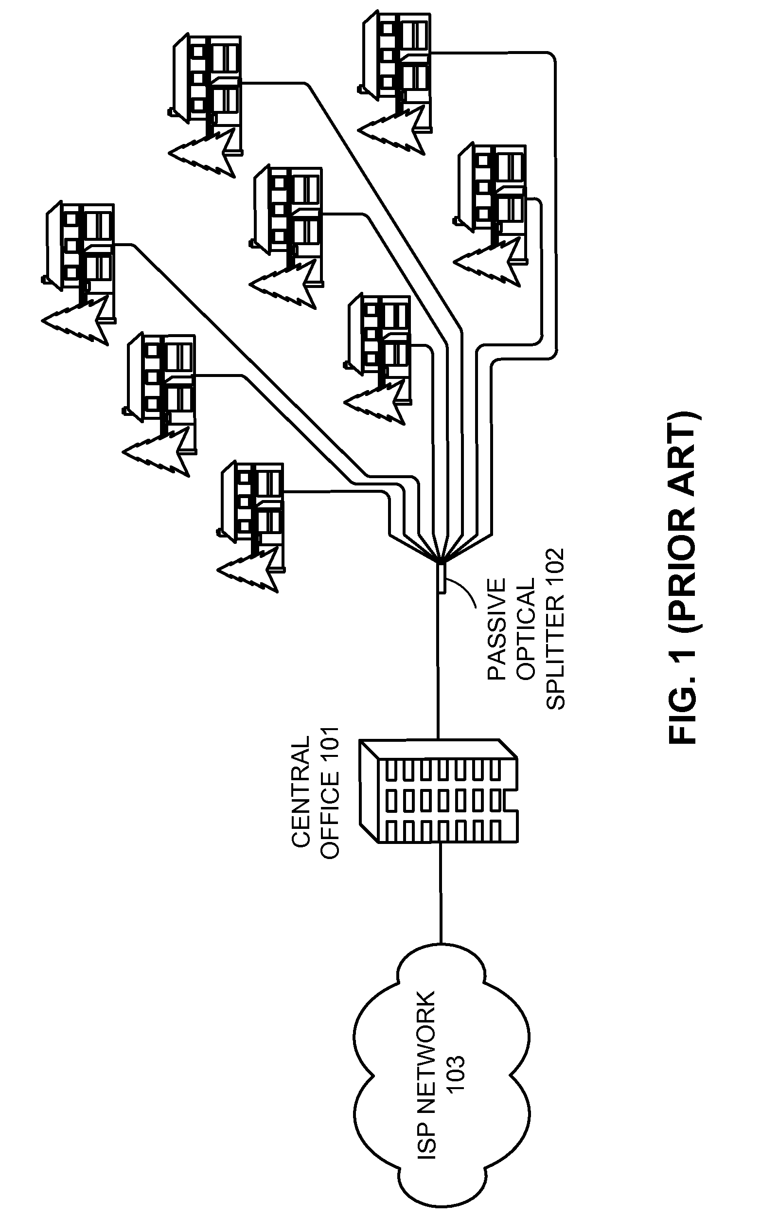
A corresponding increase in access network capacity, however, has not matched this increase in backbone network capacity.
Even with broadband solutions, such as digital subscriber line (DSL) and cable modem (CM), the limited bandwidth offered by current access networks still presents a severe bottleneck in delivering high bandwidth to end users.
Such integrated service is difficult to provide with DSL or CM technology.
Fiber trunks are susceptible to failure either because of fiber cuts or unacceptable signal degradation.
Optical components like lasers degrade or fail over time, leaving services down for undesirable durations.
The electrical components on the OLT line card and ONUs are also susceptible to complete failures.
Therefore, carriers often have to plan for redundant systems.

Method used


Image

  • Method and system for protection switching in ethernet passive optical networks
  • Method and system for protection switching in ethernet passive optical networks
  • Method and system for protection switching in ethernet passive optical networks

Examples


Embodiment Construction

[0039]The following description is presented to enable any person skilled in the art to make and use the embodiments, and is provided in the context of a particular application and its requirements. Various modifications to the disclosed embodiments will be readily apparent to those skilled in the art, and the general principles defined herein may be applied to other embodiments and applications without departing from the spirit and scope of the present disclosure. Thus, the present invention is not limited to the embodiments shown, but is to be accorded the widest scope consistent with the principles and features disclosed herein.

[0040]The operation procedures described in this detailed description may be stored on a digital-circuit readable storage medium, which may be any device or medium that can store code and / or data for use by digital circuits. This includes, but is not limited to, application-specific integrated circuits (ASICs), field-programmable gate arrays (FPGAs), semic...


PUM


Abstract

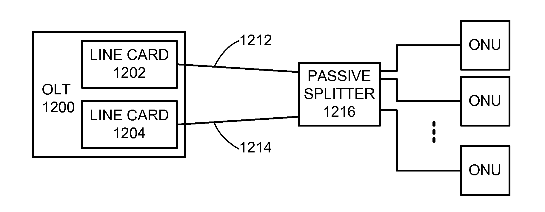
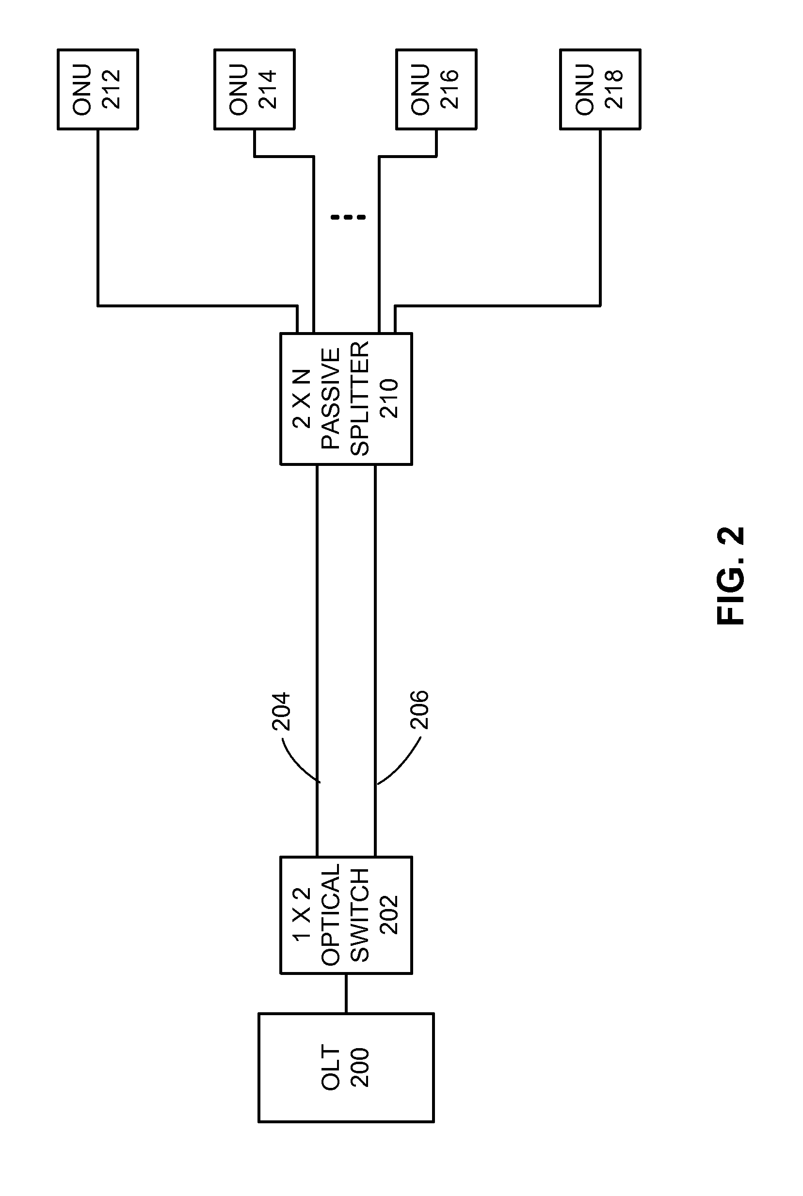
One embodiment provides a system that performs protection switching in an Ethernet passive optical network (EPON), which includes an optical line terminal (OLT) and at least one optical network unit (ONU). The system is configured with at least one redundant component for the OLT and / or ONUs, wherein the redundant component can be optical or electrical, and can be a port, line card or link. The system provides protection by detecting a failure, and switching automatically to the redundant components to reduce service disruption time. The protection switching comprises: preserving the existing configuration over the loss of at least one of a multiple-point control protocol (MPCP) message; an operations, administration and maintenance (OAM) message; and a signal on the physical layer. The system recovers from the failure without performing ONU discovery.

Description

RELATED APPLICATION[0001]This application hereby claims priority under 35 U.S.C. §119 to the following provisional patent application: U.S. Provisional Patent Application No. 61 / 107,251 filed on 21 Oct. 2008, entitled “Protection Switching in Passive Optical Networks,” by inventors Sanjay Goswami, Lawrence D. Davis, and Edward W. Boyd.BACKGROUND[0002]1. Field of the Invention[0003]This disclosure is generally related to the design of Ethernet passive optical networks. More specifically, this disclosure is related to the design of protection switching in Ethernet passive optical networks.[0004]2. Related Art[0005]In order to keep pace with increasing Internet traffic, network operators have widely deployed optical fibers and optical transmission equipment, substantially increasing the capacity of backbone networks. A corresponding increase in access network capacity, however, has not matched this increase in backbone network capacity. Even with broadband solutions, such as digital su...

Claims


Application Information

Patent Timeline
Patent Type & Authority Patents(United States)
IPC IPC(8): H04B10/032H04Q11/00H04B10/272H04B10/2581
CPCH04Q11/0067H04B10/032H04B10/272H04J2203/006H04Q2011/0081
Inventor GOSWAMI, SANJAYDAVIS, LAWRENCE D.BOYD, EDWARD W.
Owner AVAGO TECH INT SALES PTE LTD
Learn More