POS device

Active Publication Date: 2019-09-12
POSBANK
View PDF0 Cites 3 Cited by
  • Summary
  • Abstract
  • Description
  • Claims
  • Application Information

AI Technical Summary

Benefits of technology

The present invention provides a saving device attachment / detachment structure of a POS device that can remarkably reduce service unavailable time. It also allows for easy and free changing and installation of a card reader on either side of the device for increased convenience. The integrated display frame and input / output port mounting unit have a mechanically firm and efficient structure that improves manufacturing costs and process. The air current generated and efficiently circulated helps to discharge heat even during long time operation. The firm mounting to the rear surface frame of the POS device is performed through a hinge bracket, and stable fixing and easy angle adjustment is possible through appropriate friction force at the same time.

Problems solved by technology

However, since the POS terminal is necessary to be continuously used during business hours, a limitation of unavailability of the POS terminal during a time required for replacing the saving unit may cause a great limitation in which all payment works may not be processed during the time at most of small-sized stores, which use only one POS terminal.
However, in case of a left-handed person of users using the POS device, the ratio of the left-handed persons is especially great in Europe or North America, and the left-handed persons may feel inconvenience when the card reader is fixed to the above-described position.
However, the above typical invention has a limitation in manufacturing efficiency and manufacturing costs because a frame for fixing the display panel and a frame for fixing the main substrate are required to be separately manufactured, and furthermore, a process of coupling the display panel and the main substrate is required in an assembly process.
However, the typical inventions has a limitation in that a display panel, which has gradually increased in size and weight in recent years, may not be effectively supported, and an angle thereof may not be easily adjusted.

Method used


Image

  • POS device
  • POS device
  • POS device

Examples


Embodiment Construction

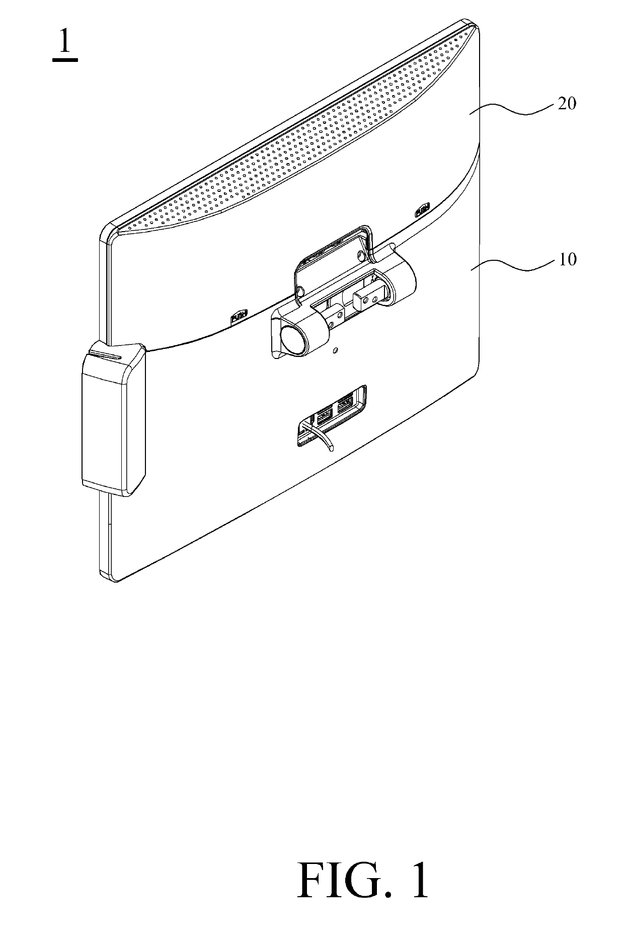
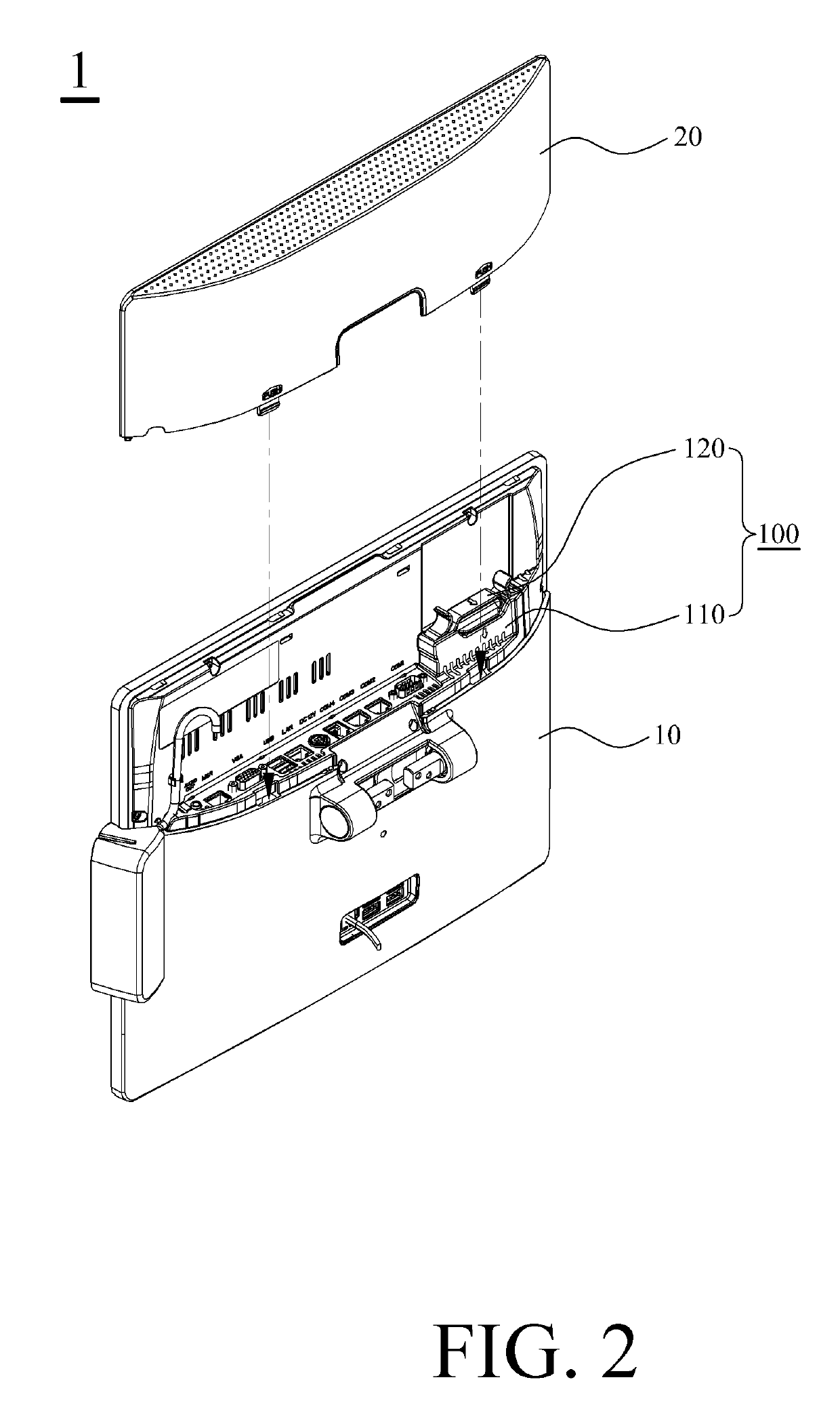
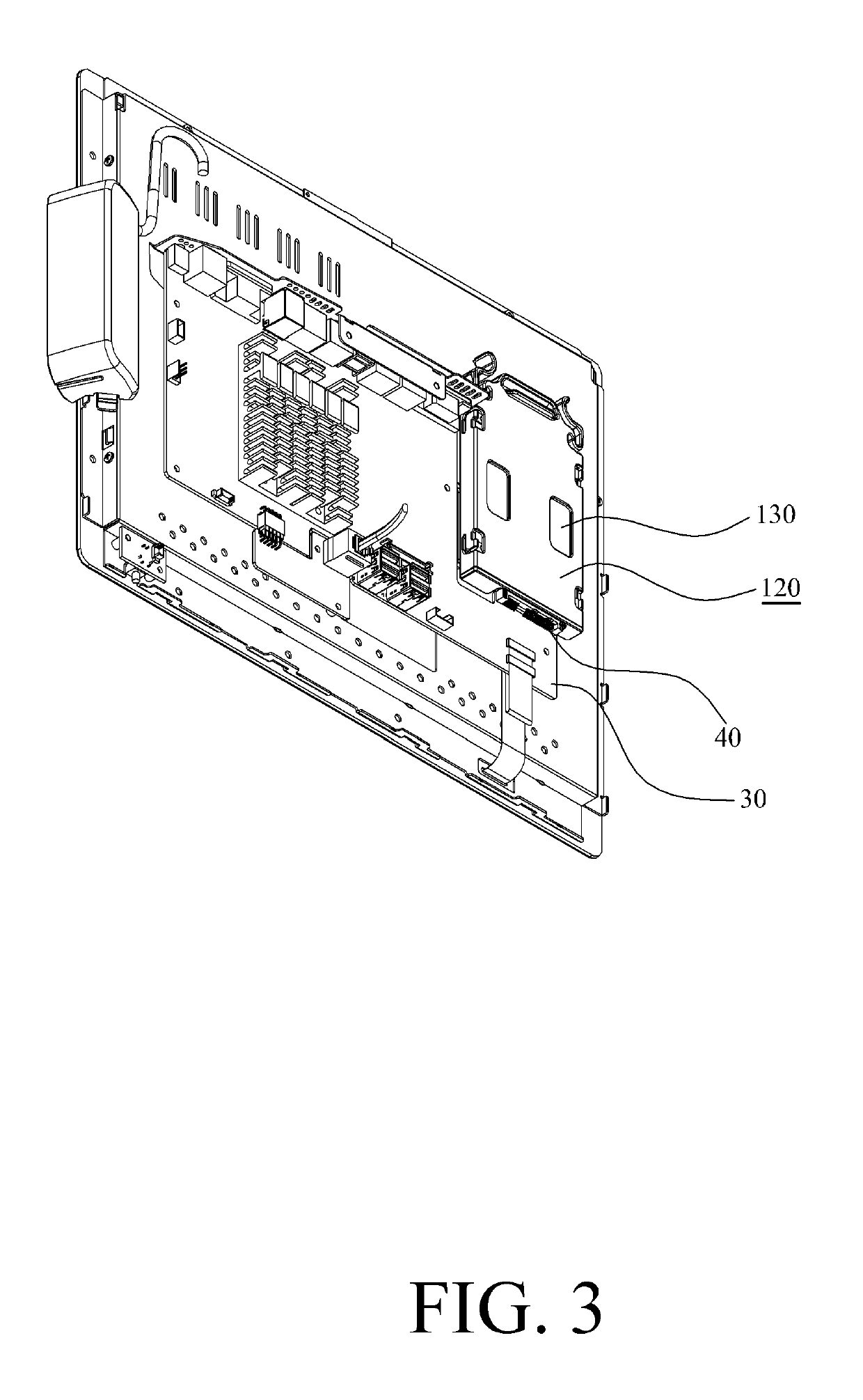
[0063]Hereinafter, a POS device according to an embodiment of the present invention will be described in detail with reference to the accompanying drawings. It is also noted that like reference numerals denote like elements in appreciating the drawings. Moreover, detailed descriptions related to well-known functions or configurations will be ruled out in order not to unnecessarily obscure subject matters of the present invention.

[0064]The POS device according to an embodiment of the present invention has improved characteristics by largely including: a saving device attachment / detachment structure 100; a card reader bidirectional mounting structure 200; a display frame 300 integrally formed with an input / output port mounting portion; and a hinge-coupling structure 400.

[0065]Firstly, the saving device attachment / detachment structure 100 will be described. As illustrated in FIG. 1, the saving device attachment / detachment structure 100 according to an embodiment of the present inventio...


PUM


Abstract

The present invention relates to a POS device, the POS device (1) having improved characteristics, largely comprising: a saving device attachment / detachment structure (100); a card reader bidirectional mounting structure (200); a display frame (300) integrally formed with an input / output port mounting portion; and a hinge-coupling structure (400).

Description

TECHNICAL FIELD[0001]The present invention relates to a POS device. In particular, the present invention relates to a POS device 1 provided with a cover 20 coupled to an upper side of a rear surface case 10 in an attachable / detachable manner, which includes:[0002]a saving device attachment / detachment structure 100 including: a saving unit mounting unit 110 formed at a portion of the rear surface case 10 and disposed at an upper side of a main substrate connector 40 mounted to a main substrate 30; a saving unit tray 120 inserted into the saving unit mounting unit 110 and coupled in an attachable / detachable manner; and a saving unit 130 including a saving unit connector 132 coupled to the saving unit tray 120 while being accommodated therein and connected to the main substrate connector 40 when the saving unit tray 120 is inserted and mounted to the saving unit mounting unit 110;[0003]a card reader bidirectional mounting structure 200 including: a mounting bracket 210 installed on at ...

Claims


Application Information

Patent Timeline
IPC IPC(8): G06K7/00G07G1/00
CPCG07G1/12G06Q20/20G06F2200/1631G07G1/0018G06F1/183G06K7/0069G06F2200/1612G06F1/181G06F1/187G06F1/20G06F2200/1613G06F1/16
Inventor EUN, DONG UK
Owner POSBANK
Why Eureka
Try Eureka