
Arrangement for and method of characterising the polarization properties of an optical system

a technology of optical systems and polarisation properties, applied in the direction of optical radiation measurement, printers, instruments, etc., can solve the problems of lack of viability and consideration of the required structural space, and achieve the effect of compact structure and reliable characterisation of polarisation properties

Active Publication Date: 2016-03-01
CARL ZEISS SMT GMBH
View PDF52 Cites 0 Cited by
  • Summary
  • Abstract
  • Description
  • Claims
  • Application Information

AI Technical Summary

Benefits of technology

The present invention provides an arrangement and method for characterizing the polarization properties of an optical system, particularly at working wavelengths in the EUV range. The arrangement includes components designed for operation in the transmission mode, which allows for a more compact structure and easier incorporation in the beam path without significant changes. Additionally, the invention allows for simultaneous or parallel measurement of the exit polarization state, which eliminates the need for scanning and reduces the time required for the measurement.

Problems solved by technology

Mirrors are used as optical components for the imaging process in projection objectives designed for the EUV range, that is to say at wavelengths of for example about 13 nm or about 7 nm, due to the lack of availability of suitable translucent refractive materials.
In that case the problem which arises in connection with the above-mentioned characterisation of the polarisation properties is that the implementation of a measurement structure like that described hereinbefore using reflective optical components can lead to considerable problems in regard to the required structural space, going as far as lack of viability.

Method used


Image

  • Arrangement for and method of characterising the polarization properties of an optical system
  • Arrangement for and method of characterising the polarization properties of an optical system
  • Arrangement for and method of characterising the polarization properties of an optical system

Examples


Embodiment Construction

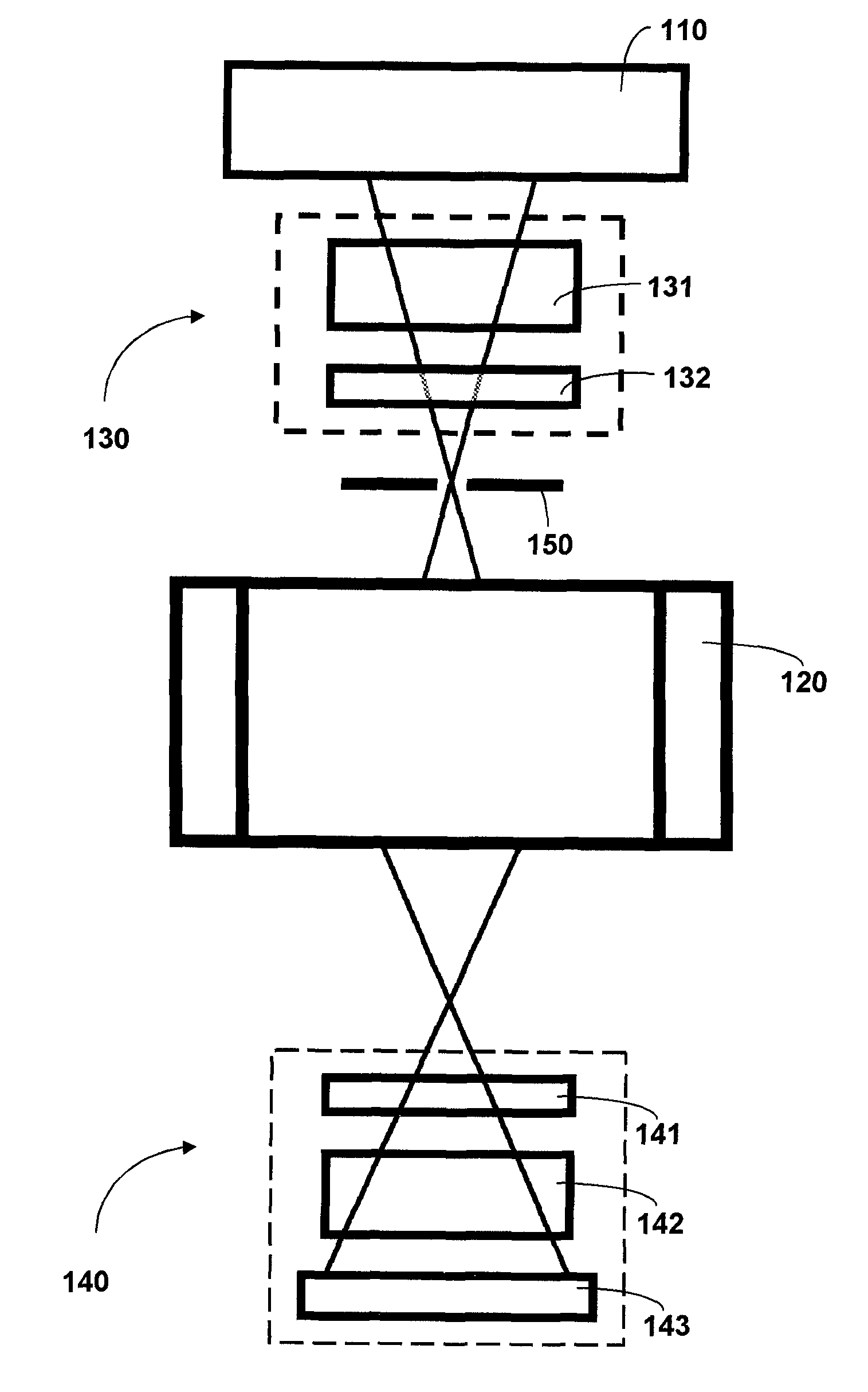
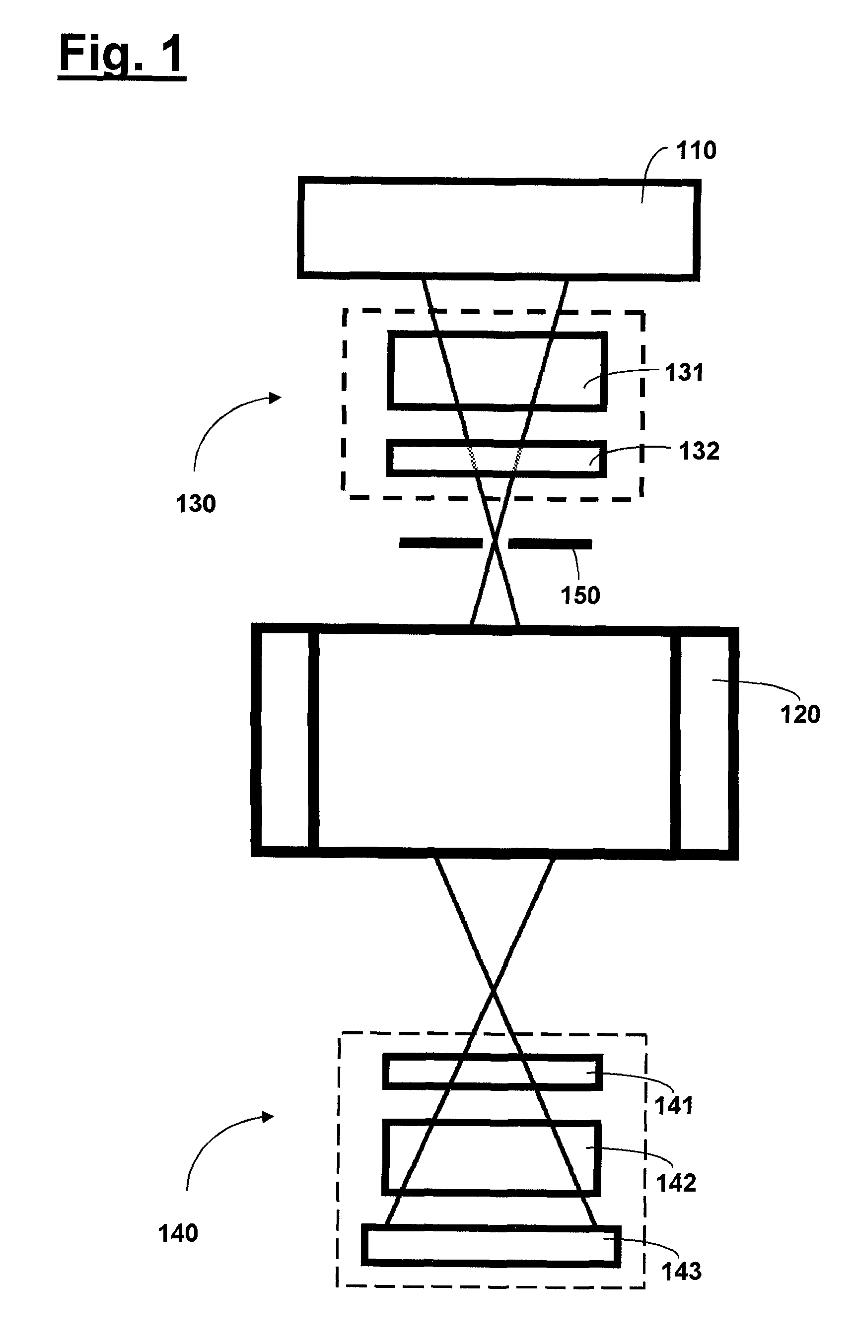
[0043]FIG. 1 firstly shows a diagrammatic view of a possible measurement structure using an arrangement according to the invention. The arrangement serves for characterising the polarisation properties of a projection objective 120 which is designed for operation in the EUV range and which with an illumination system 110 also designed for EUV forms a microlithographic projection exposure apparatus.

[0044]The method implemented using the measurement structure shown in FIG. 1 is known as such from U.S. Pat. No. 7,286,245 B2 for wavelengths in the DUV range (for example about 193 nm or about 248 nm). The subject-matter of the present application is however the use of that method in the EUV range, that is to say at wavelengths below 15 nm, wherein account is taken of the problems arising in that use as explained hereinafter by a suitable design configuration of the polarisation-optical components. More precisely the method according to the invention is distinguished by the use of wideban...


PUM

PropertyMeasurementUnit
working wavelengthaaaaaaaaaa
angleaaaaaaaaaa
angle of incidenceaaaaaaaaaa

Abstract

An arrangement for and a method of characterizing the polarization properties of an optical system, in particular an optical system of a microlithographic projection exposure apparatus. The arrangement includes at least one polarization state generator (130, 230, 330) which sets a defined polarization state of radiation incident on the optical system, and a polarization state detector (140, 240, 340) adapted to measure the exit polarization state of radiation issuing from the optical system, wherein the optical system is designed for a working wavelength of less than 15 nm, and wherein the polarization state generator and / or the polarization state detector are so designed that their polarization-optical action on an incident light beam is substantially constant over an angle spectrum of the light beam of at least 10°.

Description

[0001]The present application is a Continuation of International Application No. PCT / EP2010 / 068713, filed on Dec. 2, 2010, which claims priority of German Patent Application 10 2010 001 336.6, filed on Jan. 28, 2010. The contents of these applications are hereby incorporated by reference in their respective entireties.FIELD AND BACKGROUND OF THE INVENTION[0002]The invention concerns an arrangement for and a method of characterising the polarisation properties of an optical system.[0003]Microlithography is used for the production of microstructured components such as for example integrated circuits or LCDs. The microlithography process is carried out in what is referred to as a projection exposure apparatus having an illumination system and a projection objective. In that case the image of a mask (=reticle) illuminated by the illumination system is projected by the projection objective on to a substrate (for example a silicon wafer) which is coated with a light-sensitive layer (photo...

Claims


Application Information

Patent Timeline
Patent Type & Authority Patents(United States)
IPC IPC(8): G03B27/72G03F7/20
CPCG03F7/7085G03F7/70566G02B5/30G03F7/20
Inventor HEMPELMANN, UWEMENGEL, MARKUSHUBER
Owner CARL ZEISS SMT GMBH
Learn More