
Method and apparatus for electrostatic painting

a technology of electrostatic painting and electrostatic coating, which is applied in the direction of liquid supply arrangement, separation process, coating, etc., can solve the problems of non-homogeneity of nebulization and perfect powder spreading, quality and detachment of film, and difficulty in entrainment of film in distribution ducts, etc., to achieve better nebulization, perfect homogeneity of movement, and greater uniform thickness

Active Publication Date: 2016-02-23
EUROSIDER S DI MILLI OTTAVIO & C
View PDF2 Cites 9 Cited by
  • Summary
  • Abstract
  • Description
  • Claims
  • Application Information

AI Technical Summary

Benefits of technology

The invention uses modified air as a carrier to increase the speed of thrust and create a smoother flow, which reduces the impact of weather and other factors on the product distribution. This improves the efficiency of coating fine-powder or nanometric-powder onto surfaces. Additionally, the invention solves problems related to traditional compressed air carriers used for fine-powder coating.

Problems solved by technology

One of the known drawbacks is represented by the fact that the compressed air used entrains along with it elements that are harmful for a perfect, distribution penetration, and flow of the powder over the substrates to be coated, such as, for example, humidity, particles of hydrocarbons due to the compression of the air and particles in suspension present in the atmospheric air.
This problem is much felt in so far as it gives rise to microbubbles that form between the substrate and the film of coating, and over time cracks may arise in the film itself with consequent problems of quality and detachment of the film.
From these premises there follow the problems typical of conventional powder coating, which uses air without any treatment as carrier fluid for the steps of management of the powder fluidized bed, entrainment, nebulization, and peristaltic recovery.
The contamination by humidity, the vesicular pollution from the hydrocarbon residue (that is, pollution from the hydrocarbon residue in the form of vesicles), as likewise the oily organic substances, moreover yield as a consequence formation of aggregates and accumulations of powder, difficulty of entrainment thereof in the distribution ducts, and non-homogeneity of nebulization and perfect spreading of the powder and lack of uniformity in the thicknesses with consequent difficulty in flow of the coating.
Furthermore, typical of electrostatic powder coating or liquid coating is the formation, in the corners or at the ends of perforations present in the product to be coated, of the Faraday-cage effect, which does not allow uniformity or a perfect distribution, penetration, and flow of the powder, in certain cases causing the absence of coating product, such as for example in the corners or fins typical of electric motors or of heating bodies such as radiators or components of electrical household appliances and steel structural work in general.
Also known are the difficulties in currently available systems of electrostatically charging very fine powder in order to obtain high-quality finishes.
It is in fact difficult to get fine-grain powder and nanometric powder to be charged and to maintain the charge prior to impact on the products for a perfect nebulization and homogeneous distribution over the surfaces or products of various nature under the effect of the electrostatic charge.
Also known are the problems in systems for fine-powder or nanometric-powder coating that use as carrier traditional compressed air, which entrains along with it pollutant elements (amongst which particles of hydrocarbons, particles of water, and pollutant dust of various nature) that render difficult perfect distribution, penetration, and flow of the powder over the surfaces.
In spite of all the aforesaid drawbacks, known systems in any case use as carrier fluid for the powder mere compressed air even though it entrains along with it particles of humidity, particles of oil vapours, and volatile particles present in the atmosphere, thus causing the problems referred to above.

Method used


Image

  • Method and apparatus for electrostatic painting
  • Method and apparatus for electrostatic painting
  • Method and apparatus for electrostatic painting

Examples


Embodiment Construction

[0039]With reference to the drawings, an apparatus and a method according to the invention are now described.

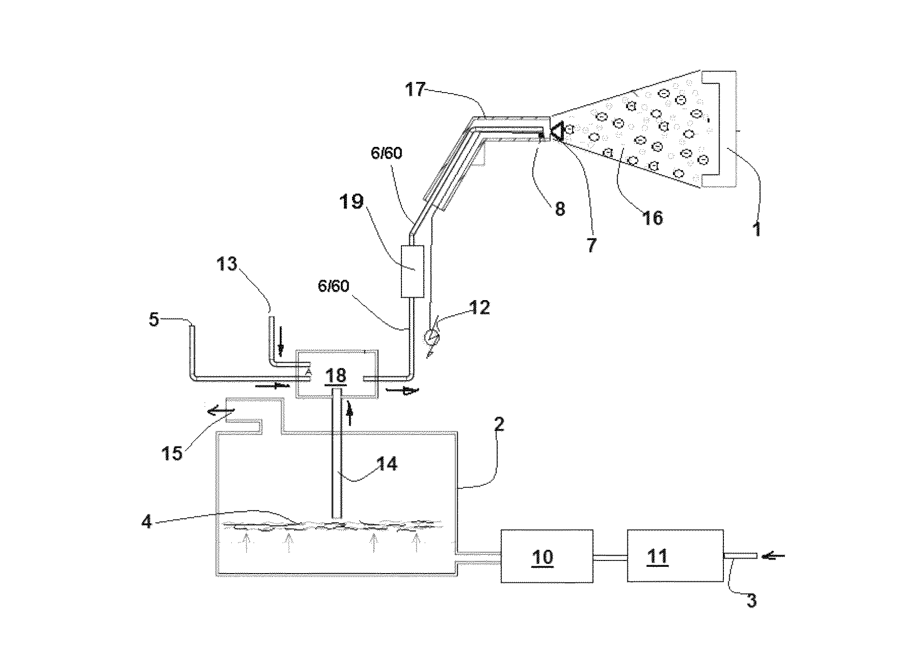
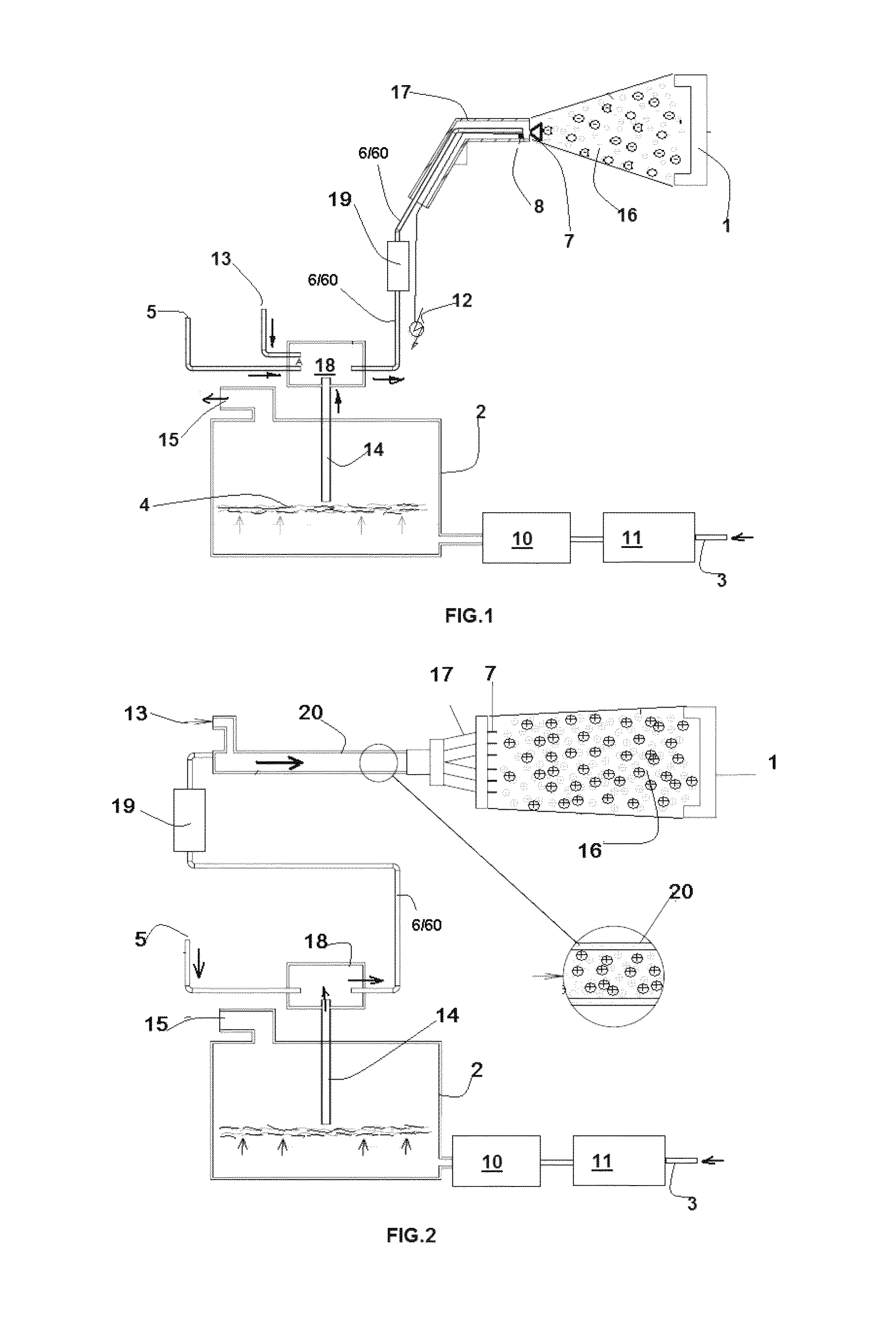
[0040]In the example of embodiment illustrated, a source 3 of a fluidifying fluid is provided, which gives out into a container 2 containing an amount of coating powder 4.

[0041]The fluid has the function of maintaining in dispersed and non-agglomerated form the powder that is to be sprayed on a substrate to be coated 1.

[0042]The container 2 communicates downstream with an atomizer device 18, which in turn communicates with a source 13 of atomization / nebulization fluid and a source 5 of a carrier fluid under pressure, which, via an appropriate pipe 6, is to convey the flow of carrier fluid and atomized powder to a spray nozzle 7 of a gun 17, capable of delivering a coating fan 16.

[0043]Moreover provided upstream of the nozzle 7 are means 8, in themselves known, for electrostatically charging the flow of carrier fluid and powder.

[0044]In different embodiments, the means 8 may b...


PUM

PropertyMeasurementUnit
pressureaaaaaaaaaa
pressureaaaaaaaaaa
temperatureaaaaaaaaaa

Abstract

A device and method for electrostatic powder coating include: obtaining continuously a working fluid constituted by air deprived of undesirable substances; supplying the working fluid, between 0.5 bar and 10 bar, in a container containing an amount of coating powder; extracting from the container; a first flow made up of working fluid and powder; atomizing the first flow with working fluid at a pressure of between 0.5 bar and 10 bar; supplying working fluid at a pressure of between 0.5 bar and 10 bar to create a second transport flow made up of working fluid and atomized powder; charging the second flow electrostatically under pressure; and sending the second electrostatically charged flow of working fluid and atomized powder onto a substrate, at a temperature of between −15° C. and +45° C., and a device and method for electrostatic painting including heating / cooling temperature adjustment of the painting mixture.

Description

SECTOR OF THE INVENTION[0001]The present invention relates to a method and an apparatus for systems for electrostatic powder coating that exploits the use of a carrier fluid constituted by air deprived of undesirable substances, together with ionization and heat conditioning of said carrier fluid.[0002]In greater detail, the invention relates to a method and an apparatus for coating that uses as paint-carrier fluid a mixture rich in nitrogen / oxygen / argon obtained continuously from compressed air during coating.PRIOR ART[0003]As is known, the current state of the art in powder-coating systems envisages a corona-effect electrostatic-spray system, where positioned in the terminal part of the guns are one or more needles that yield a charge to the powder to be attracted onto the products to be coated, or else with the system known as “tribo” with which the powder is charged by rubbing in a purposely provided tube.[0004]In either case, the operating coating steps envisage entrainment of ...

Claims


Application Information

Patent Timeline
Patent Type & Authority Patents(United States)
IPC IPC(8): B05B5/00B05B5/03B05B5/16B05B15/12
CPCB05B5/001B05B5/032B05B5/1683B05B15/1229B05B14/48B05B7/2491B05D1/06B05B5/03B05B5/08B01D53/02B01D53/229B01D2053/224B01D2253/116
Inventor MILLI, OTTAVIO
Owner EUROSIDER S DI MILLI OTTAVIO & C
Learn More