
Liquid distribution trough for use in towers in sulphuric acid and carbon capture plants

a technology of liquid distribution troughs and carbon capture plants, which is applied in the direction of dispersed particle separation, separation processes, chemistry apparatuses and processes, etc., can solve the problems of difficult to obtain even liquid distribution, relatively expensive, and seldom used pan types, and achieves simple and convenient feed conduits

Active Publication Date: 2016-02-16
CHEMETICS
View PDF45 Cites 11 Cited by
  • Summary
  • Abstract
  • Description
  • Claims
  • Application Information

AI Technical Summary

Benefits of technology

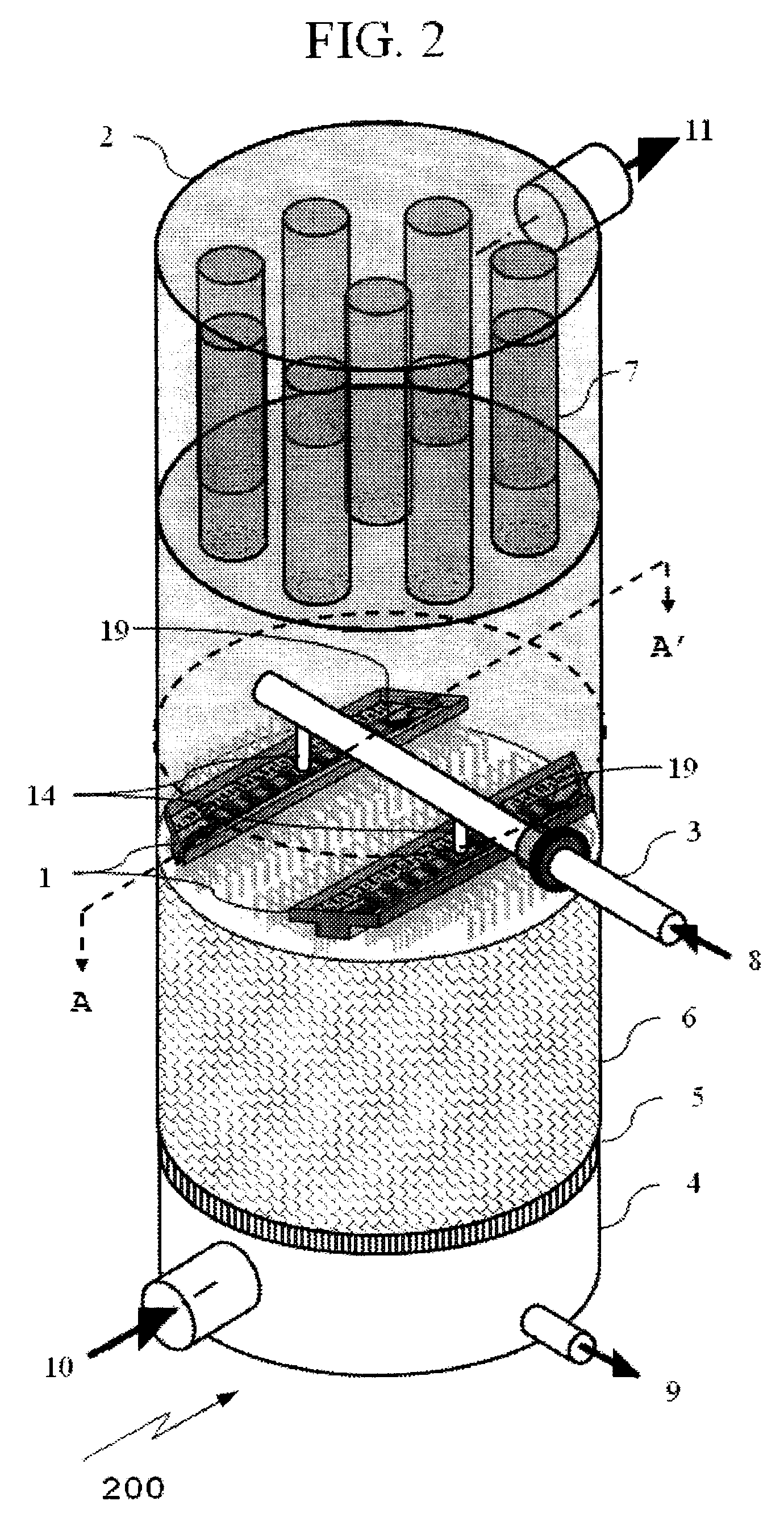
The present invention provides a trough distributor with a simple and convenient feed conduit means while also providing for an even distribution of liquid. It reduces cleaning frequency by preventing sedimentation that will block discharge orifices. The invention minimizes the number of feed liquid entry points for individual troughs and keeps fine solids suspended in the flow streams throughout the distributor. The invention may be used for reduced distributor size in many applications, or for high flow capacity. It provides a single entry point for each distribution trough in a weir-type or submerged-orifice-type trough distributor. The invention also provides an improved distributor that does not require a network of feed conduits or a feed conduit with branching feed conduits. The invention includes a flow direction change and energy dissipation systems that prevent solids accumulation and improve distribution of liquid throughout the distributor. The invention is beneficial to both submerged orifice type and weir type distributors.

Problems solved by technology

The tray or pan type is seldom employed in towers larger than 1.5 meters diameter as they are relatively expensive and generally limited to smaller gas flows.
However, disadvantages of pressurized pipe distributors include difficulty obtaining even liquid distribution when the inlet liquid also contains some gas or solids; requiring disassembly for cleaning; and producing fine liquid drops which are carried over with upward-flowing, high velocity gas.
Weir-type distributors have overflow weirs at or near the top of the trough, and are very sensitive to even small variations in liquid height having a large detrimental impact on uniform distribution.
However, orifices are more prone to becoming blocked with suspended solids that settle out when compared to weir-type distributors.
However, this barrier can be eroded off if the flow becomes turbulent.
Ductile iron troughs or pipes were also designed with large corrosion allowances making them very heavy.
Although means such as strainers or filters are employed to remove solids, such devices are not perfect and, in the sulphuric acid industry, the materials of construction suitable for filter elements have limited life.
The solids in the liquid can build up deposits in distributors that cause mal-distribution and a periodic cleaning the equipment is required with subsequent loss of production.
However, as liquid capacity is increased through a trough distributor, i.e. reducing size with higher velocities, difficulty arises in maintaining a calm liquid surface at a uniform height above each discharge exit; thus different methods of introducing the liquid into the troughs at multiple entrance points have been employed in order to maintain low velocity and minimal disturbance of the liquid surface.
However, the additional feed conduits reduce cost-effectiveness and are inconvenient when cleaning is required.

Method used


Image

  • Liquid distribution trough for use in towers in sulphuric acid and carbon capture plants
  • Liquid distribution trough for use in towers in sulphuric acid and carbon capture plants
  • Liquid distribution trough for use in towers in sulphuric acid and carbon capture plants

Examples


example

[0104]The successful functioning of the present invention was discovered from experimental testing conducted using a small scale distributor trough. The small scale model was made of clear material to allow observation of liquid flow within trough 1 and to determine the overall performance of the distributor improvements compared to an equivalently sized model according to the prior art. The effects of individual features used in improved distributor 1 were also observed by inserting and removing various components. Test work was used to adjust computer simulation models for accurate reproduction and computer simulation gave further insight into the flow patterns and effects of experimentally added features.

[0105]Each added feature used in the improved distributor 2 was insufficient on its own per se to improve the overall performance of distributor 1. Thus, starting from an empty trough shell, each feature addressed a performance difficulty but often created a new one. The complete...


PUM


Abstract

A liquid distribution trough contained within a tower for the purpose of mass or thermal exchange between at least a first liquid and a second fluid; the trough having an upper section and a lower section; the lower section for receiving the first liquid; a horizontal dividing member separating the upper section from the lower section and having at least one dividing member portion defining an aperture to allow for passage of the liquid fluid from the lower section to the upper section; a feed conduit means in communication with the lower section to provide feed first liquid flow to the lower section; the lower section having at least one inlet portion defining a liquid inlet in communication with the feed conduit means; and a first baffle adjacent the inlet portion operably impacted by the first liquid flow and to hinder preferential flow along the walls of the trough and the dividing member. The trough and tower are of particular value in a sulphuric acid plant and a carbon dioxide capture plant.

Description

FIELD OF THE INVENTION[0001]This invention relates to distribution troughs, particularly a plurality and network thereof; to distribution towers comprising said distribution troughs and particularly for use as absorption and drying towers in the sulphuric acid contact process; and carbon dioxide capture.BACKGROUND OF THE INVENTION[0002]Distributors are used to distribute a liquid throughout an area from a liquid feed source. Specifically, in an absorption tower a liquid is distributed across the top of a packed bed within the tower. A gas flows through the tower in generally counter-current flow to the liquid but it can also flow co-currently. The liquid is used to absorb a chemical out of the gas or a gas is used to strip a volatile component from a liquid. Examples in sulphuric acid production include absorption of sulphur trioxide gas, SO3, or of water vapour into a strong sulphuric acid solution; also the air stripping of sulphur dioxide, SO2, from a sulphuric acid stream. An ex...

Claims


Application Information

Patent Timeline
Patent Type & Authority Patents(United States)
IPC IPC(8): B01D3/00B01D53/18B01D53/26
CPCB01D3/008B01D53/185B01D53/263Y02P70/34Y02P70/10Y02C20/40Y02A50/20
Inventor NORTON, DANIEL S.PEREZ, ORLANDO G.DRACKETT, THOMAS S.STERENBERG, DAVID J.
Owner CHEMETICS
Learn More