Press machine

a press machine and ram technology, applied in the field of press machines, can solve the problems of difficult to stop the ram completely, difficult to control the speed, and difficulty in halting the ram down, so as to reduce the number of control valves used, reduce the number of control valves, and reduce the driving force.

Active Publication Date: 2015-09-22
MURATA MASCH LTD
View PDF9 Cites 2 Cited by
  • Summary
  • Abstract
  • Description
  • Claims
  • Application Information

AI Technical Summary

Benefits of technology

[0011]According to the above described construction, by the motor driven lifting unit outputting a high speed, low load driving force, the die on the movable side is driven from the standby position towards the drive system changeover position and, by the hydraulically driven lifting unit outputting a low speed, high load driving force, the die on the movable side is driven from the drive system changeover position towards the bottom dead center position. Accordingly, the high speed and stabilized movement of the die on the movable side and the assured press work can be accomplished. Since the motor driven lifting mechanism does not participate in the pressurized drive of the die on the movable side, a motor driven lifting mechanism having a small capacity can be selected. For this reason, the inertia is small and the abstract stoppage performance is good. Also, when the die on the movable side is held at the standby position, it is supported by the motor driven lifting unit and, therefore, the die will not be affected by a leakage of oil in the hydraulically driven lifting unit.
[0013]The use of the counterbalance makes it possible to selectively lower and lift the die on the movable side with a small driving force, and, therefore, the motor driven lifting unit can be compactized, and also, the energy efficiency can be increased.
[0015]The hydraulically driven lifting unit of the structure described above is such that when the oil is supplied by the oil pump to the first cylinder chamber, the hydraulic cylinder is actuated in a predetermined direction, accompanied by the movement of the die on the movable side from the drive system changeover position towards the bottom dead center position. At this time, the prefill valve acts to avoid an undesirable outflow of the oil from the first cylinder chamber. When the oil is discharged by the oil pump from the first cylinder chamber, the hydraulic cylinder is actuated in a reverse direction by the pressurized oil accumulated within the accumulator, allowing the die on the movable side to return from the bottom dead center position back to the drive system changeover position. At this time, the prefill valve acts to permit the outflow of the oil from the first cylinder chamber. The use of the accumulator is effective to reduce the number of control valves used and also to simplify the hydraulic circuit. This construction makes it possible to adjust the number of revolutions of the oil pump so that the operating position of the die on the movable side can be fixed accurately to accomplish the proper press work.
[0019]If the motor driven lifting unit makes use of the ball screw mechanism, the die on the movable side can be accurately driven at a high speed while the structure thereof is simplified. Also, if the combination of the motor driven lifting unit and the hydraulically driven lifting unit is provided in a pair one on each of left and right positions, the die on the movable side can be elevated while the die on the movable side is retained in a properly leftward or rightward tilted fashion. The hydraulically driven lifting unit that is used in the practice of a high pressure press work is more bulky than the motor driven lifting unit. For this reason, if the hydraulically driven lifting unit, rather than the motor driven lifting unit, is disposed on an inner side, the maintenance of the lifting mechanism can be easily performed from leftward or rightward outside.
[0021]In the hydraulically driven lifting unit of the above described construction, when the hydraulic cylinder is actuated by the high speed hydraulic circuit, the die on the movable side is moved from the standby position towards the hydraulic circuit changeover position, but when the hydraulic cylinder is actuated by the low speed hydraulic circuit, the die on the movable side is moved from the hydraulic circuit changeover position towards the bottom dead center position. Accordingly, the high speed and stabilized movement of the die on the movable side and the assured press work can be accomplished.

Problems solved by technology

In general, the hydraulic drive system is known to be effective in providing a high power output, but difficult in controlling the speed, particularly in controlling a high speed drive.
For this reason, according to the hydraulic drive system, a substantial amount of time is required to drive the ram from a standby position to a press start position, thus posing a problem in operating efficiency.
In addition, the hydraulic drive system occasionally accompanies a leakage of oil and, therefore, it is difficult to halt the lowering of the ram completely.
On the other hand, the motor drive system poses such a problem that difficulty is often encountered with in applying a high load and does therefore have limitations in use thereof, one of which includes an incapability of handling with heavy plates.
Also, in view of the structure of the motion translating mechanism, the motor drive system is generally considered difficult to accomplish a speed changeover between a high speed and a low speed.
For this reason, the abrupt stoppage performance appears to become untolerable.
It has, however, been found that if the ball screw mechanism is large in size, the inertias is large during a high speed drive, resulting in an increase of the stopping distance.
Also, because of the pressurization accomplished by the ball screw mechanism, it is incapable of being applied to a large-size press brake.

Method used


Image

  • Press machine
  • Press machine
  • Press machine

Examples


Embodiment Construction

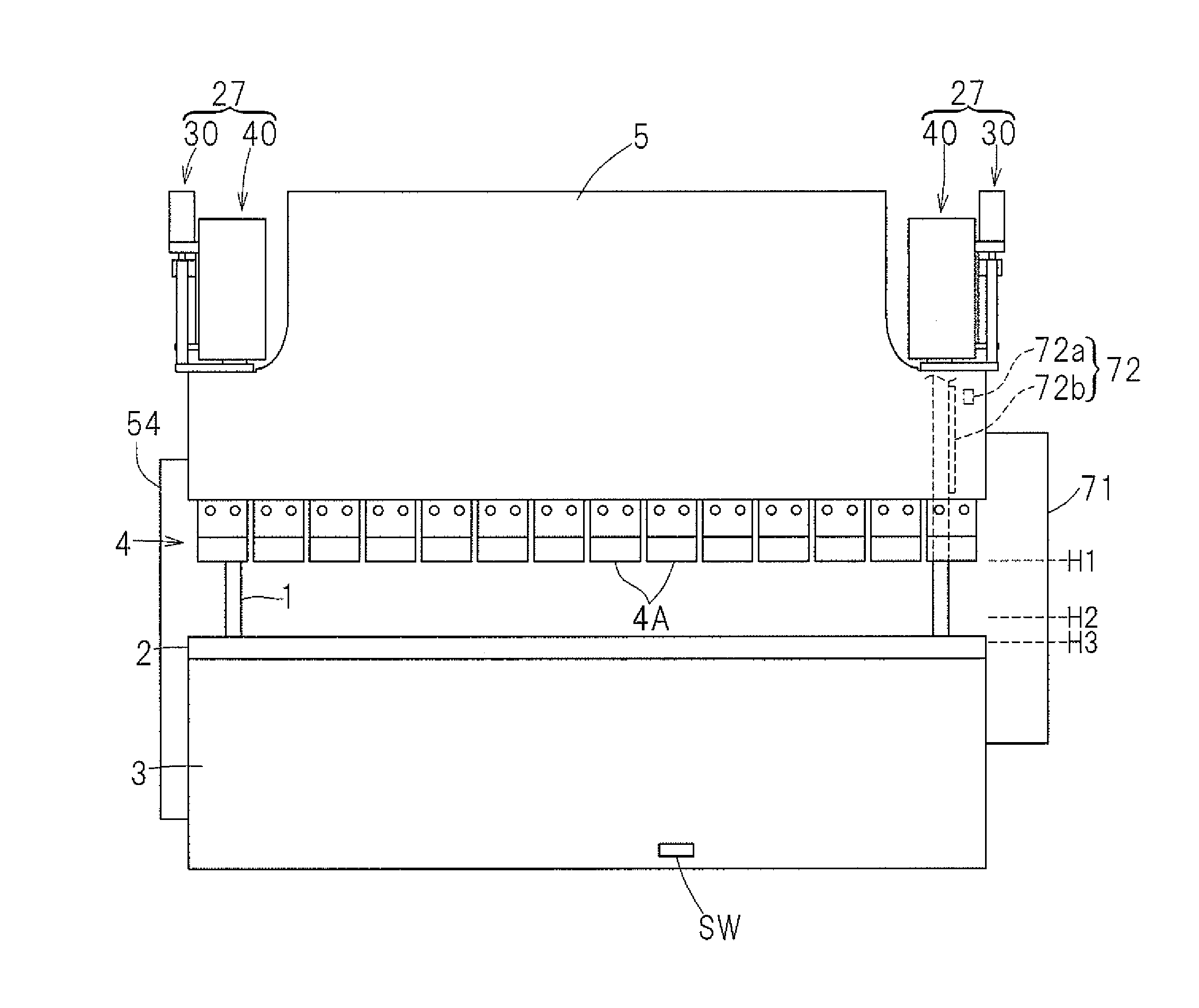
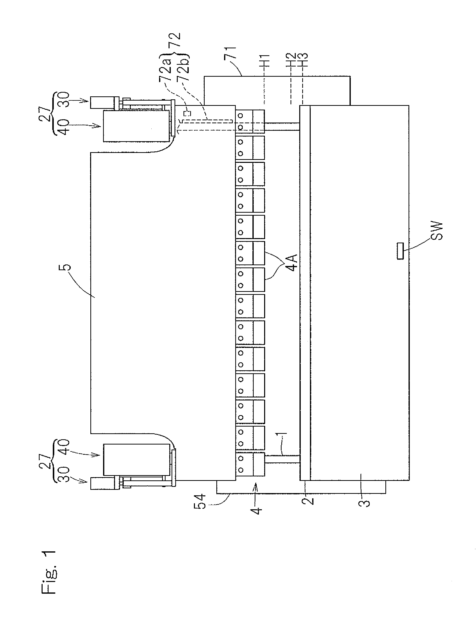
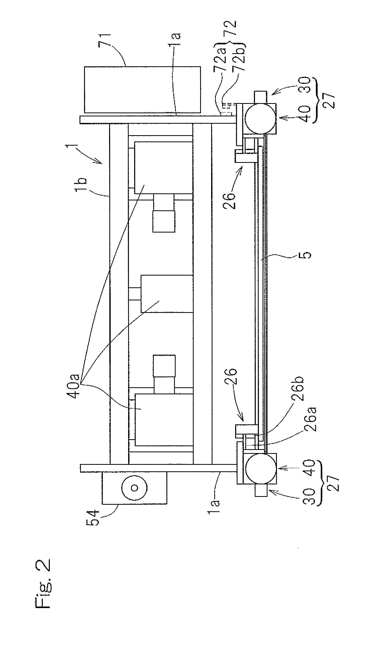
[0039]Preferred embodiments of the present invention will now be described in detail with particular reference to the accompanying drawings. FIG. 1 illustrates a front elevational view of a press machine designed in accordance with a preferred embodiment of the present invention, FIG. 2 is a top plan view of such press machine, and FIG. 3 is a side view of such press machine. The illustrated press machine is a press brake, which includes a main body frame 1 having its front surface side provided with a table 3 to support a lower die 2, which may be a die on the stationary side, i.e., a stationary die, and a ram 5 defining and serving as a movable support member to support an upper die 4, which may be a die on the movable side, i.e., a movable die. The table 3 is fixed in position relative to the main body frame 1, but the ram 5 is movable up and down with its left and right side portions guided by respective guide units 26 as shown in FIGS. 2 and 3. The lower die 2 preferably is a u...


PUM

PropertyMeasurementUnit
weightaaaaaaaaaa
driving forceaaaaaaaaaa
pressureaaaaaaaaaa

Abstract

A press machine includes a lifting mechanism that selectively lowers and lifts a die on a movable side. The lifting mechanism includes a motor driven lifting unit using a servomotor as a drive source thereof, and a hydraulically driven lifting unit using a hydraulic actuator as a drive source thereof. The lifting mechanism is controlled so as to enable the motor driven lifting unit to move the die on the movable side from a standby position to a drive system changeover position immediately before a press start position at which the die on the movable side starts contacting a workpiece to be processed and so as to enable the hydraulically driven lifting unit to move the die on the movable side from the drive system changeover position to a top dead center position.

Description

CROSS REFERENCE TO THE RELATED APPLICATION[0001]This application is based on and claims Convention priority to Japanese patent application No. 2010-201879, filed Sep. 9, 2010, the entire disclosure of which is herein incorporated by reference as a part of this application.BACKGROUND OF THE INVENTION[0002]1. Field of the Invention[0003]The present invention relates to a press machine such as, for example, a press brake.[0004]2. Description of the Related Art[0005]When a press brake is classified according to a drive system of a ram, two types are generally available; a hydraulic drive system utilizing a hydraulic cylinder and a motor drive system utilizing a servo motor. The motor drive system is of a type in which a revolving motion of a servomotor is translated into a linear motion by means of a motion translating mechanism such as, for example, a ball screw mechanism. In addition to those two systems referred to above, a composite drive system utilizing the servomotor and the hydr...

Claims


Application Information

Patent Timeline
Patent Type & Authority Patents(United States)
IPC IPC(8): B21D5/02B30B15/02B30B15/18B30B15/16B30B1/32B30B1/18B30B1/23
CPCB21D5/02B21D5/0272B30B1/18B30B1/23B30B1/32B30B15/026B30B15/16B30B15/163B30B15/183B30B15/068
Inventor IMAEDA, WATARUWATANABE, AKINOBU
Owner MURATA MASCH LTD
Why Eureka
Try Eureka