Press machine

Active Publication Date: 2013-06-20
MURATA MASCH LTD
View PDF1 Cites 1 Cited by
  • Summary
  • Abstract
  • Description
  • Claims
  • Application Information

AI Technical Summary

Benefits of technology

The patent describes a press with a motor driven lifting system and a hydraulically driven lifting system. The motor driven unit drives the die at high speed and low load, while the hydraulically driven unit drives the die at low speed and high load. The hydraulic system includes a accumulator to control the movement of the die and a prefill valve to prevent oil leakage. The use of a counterbalance allows for easy lifting and lowering of the die. The combination of motor and hydraulic units offers high speed and stability, and the use of a ball screw mechanism simplifies the design. The hydraulically driven lifting unit allows for elevation of the die while maintaining its position, and the use of a low speed hydraulic circuit allows for high-speed and stabilized movement of the die.

Problems solved by technology

In general, the hydraulic drive system is known to be effective in providing a high power output, but difficult in controlling the speed, particularly in controlling a high speed drive.
For this reason, according to the hydraulic drive system, a substantial amount of time is required to drive the ram from a standby position to a press start position, thus posing a problem in operating efficiency.
In addition, the hydraulic drive system occasionally accompanies a leakage of oil and, therefore, it is difficult to halt the lowering of the ram completely.
On the other hand, the motor drive system poses such a problem that difficulty is often encountered with in applying a high load and does therefore have limitations in use thereof, one of which includes an incapability of handling with heavy plates.
Also, in view of the structure of the motion translating mechanism, the motor drive system is generally considered difficult to accomplish a speed changeover between a high speed and a low speed.
For this reason, the abrupt stoppage performance appears to become untolerable.
It has, however, been found that if the ball screw mechanism is large in size, the inertias is large during a high speed drive, resulting in an increase of the stopping distance.
Also, because of the pressurization accomplished by the ball screw mechanism, it is incapable of being applied to a large-size press brake.

Method used


Image

  • Press machine
  • Press machine
  • Press machine

Examples


Embodiment Construction

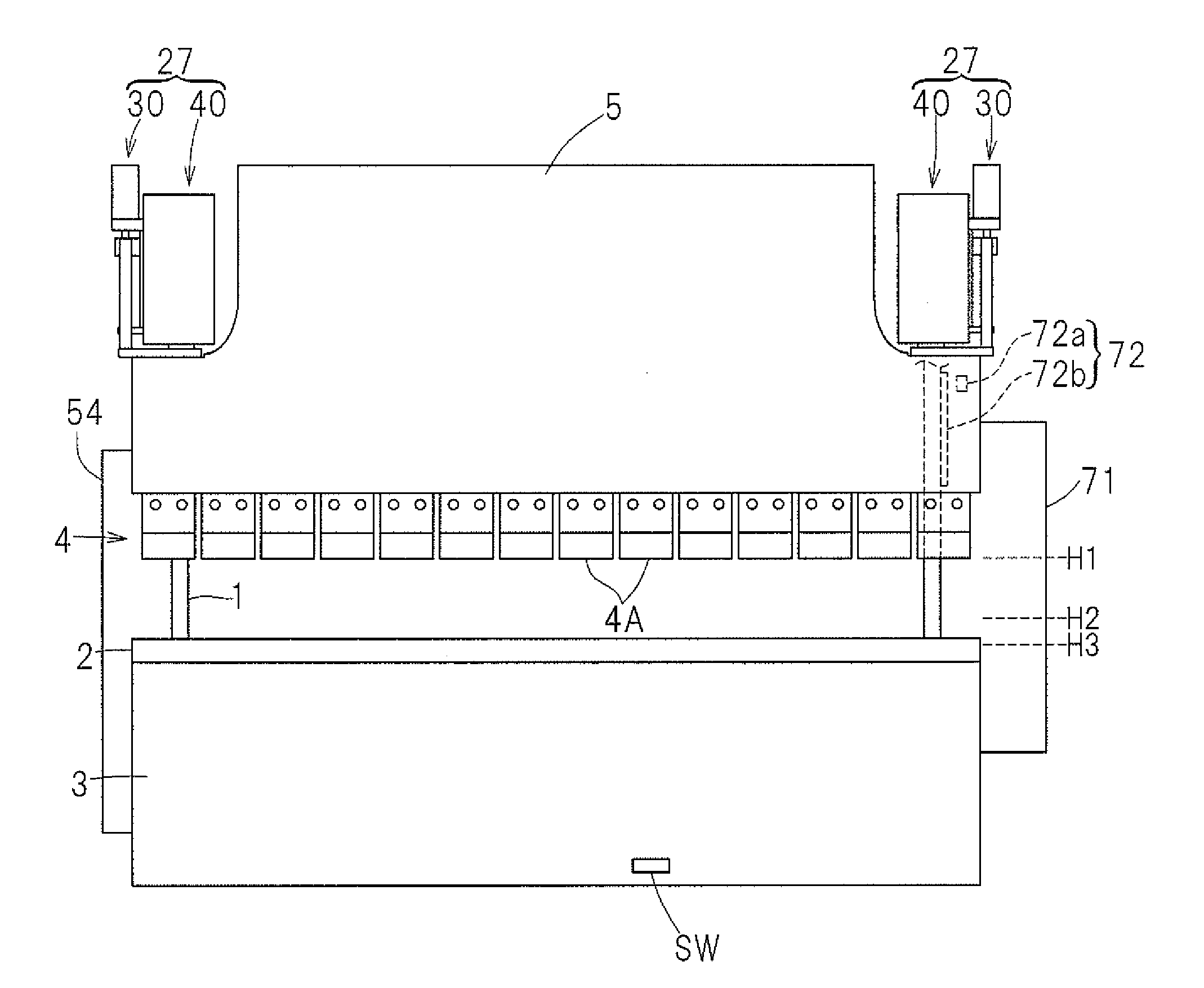
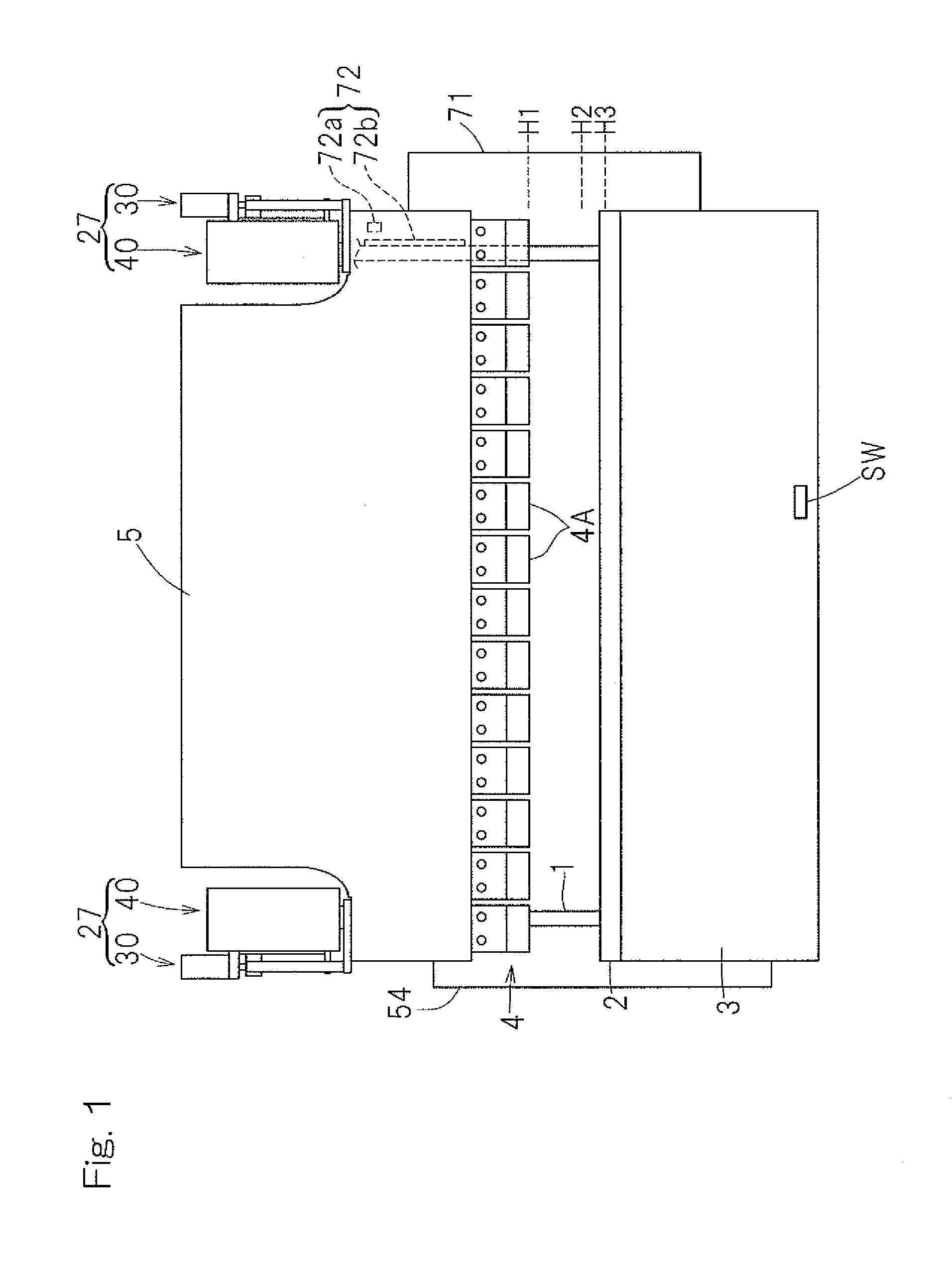
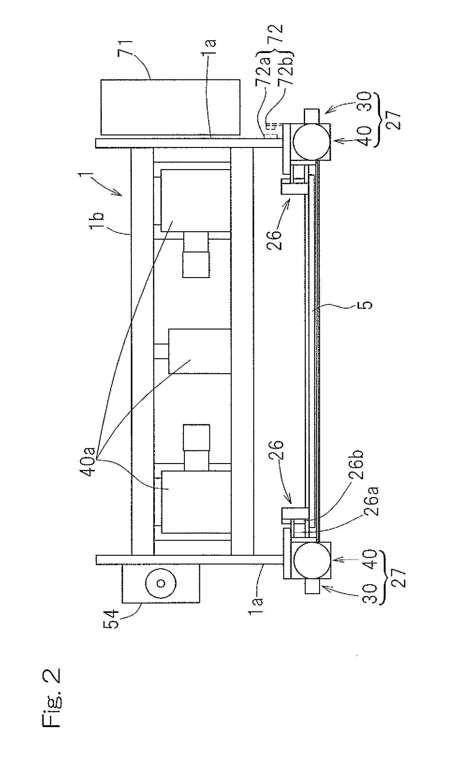
[0039]Preferred embodiments of the present invention will now be described in detail with particular reference to the accompanying drawings. FIG. 1 illustrates a front elevational view of a press machine designed in accordance with a preferred embodiment of the present invention, FIG. 2 is a top plan view of such press machine, and FIG. 3 is a side view of such press machine. The illustrated press machine is a press brake, which includes a main body frame 1 having its front surface side provided with a table 3 to support a lower die 2, which may be a die on the stationary side, i.e., a stationary die, and a ram 5 defining and serving as a movable support member to support an upper die 4, which may be a die on the movable side, i.e., a movable die. The table 3 is fixed in position relative to the main body frame 1, but the ram 5 is movable up and down with its left and right side portions guided by respective guide units 26 as shown in FIGS. 2 and 3. The lower die 2 preferably is a u...


PUM

PropertyMeasurementUnit
Weightaaaaaaaaaa
Pressureaaaaaaaaaa

Abstract

A press machine includes a lifting mechanism that selectively lowers and lifts a die on a movable side. The lifting mechanism includes a motor driven lifting unit using a servomotor as a drive source thereof, and a hydraulically driven lifting unit using a hydraulic actuator as a drive source thereof. The lifting mechanism is controlled so as to enable the motor driven lifting unit to move the die on the movable side from a standby position to a drive system changeover position immediately before a press start position at which the die on the movable side starts contacting a workpiece to be processed and so as to enable the hydraulically driven lifting unit to move the die on the movable side from the drive system changeover position to a top dead center position.

Description

CROSS REFERENCE TO THE RELATED APPLICATION[0001]This application is based on and claims Convention priority to Japanese patent application No. 2010-201879, filed Sep. 9, 2010, the entire disclosure of which is herein incorporated by reference as a part of this application.BACKGROUND OF THE INVENTION[0002]1. Field of the Invention[0003]The present invention relates to a press machine such as, for example, a press brake.[0004]2. Description of the Related Art[0005]When a press brake is classified according to a drive system of a ram, two types are generally available; a hydraulic drive system utilizing a hydraulic cylinder and a motor drive system utilizing a servo motor. The motor drive system is of a type in which a revolving motion of a servomotor is translated into a linear motion by means of a motion translating mechanism such as, for example, a ball screw mechanism. In addition to those two systems referred to above, a composite drive system utilizing the servomotor and the hydr...

Claims


Application Information

Patent Timeline
IPC IPC(8): B21D5/02B30B1/23
CPCB21D5/0272B30B15/026B21D5/02B30B1/23B30B15/183B30B1/32B30B15/16B30B15/163B30B1/18B30B15/068
Inventor IMAEDA, WATARUWATANABE, AKINOBU
Owner MURATA MASCH LTD
Why Eureka
Try Eureka