
Air-floating-type flexible pulling butt joint assembling platform

An assembly platform, air-floating technology, used in metal processing, metal processing equipment, manufacturing tools, etc., can solve the problems of poor flexibility, poor docking compliance, and complex mechanism, so as to improve flexibility adaptability and improve docking compliance. degree, the effect of simplifying the degree of complexity

Active Publication Date: 2017-06-13
HARBIN INST OF TECH +1
View PDF9 Cites 20 Cited by
  • Summary
  • Abstract
  • Description
  • Claims
  • Application Information

AI Technical Summary

Problems solved by technology

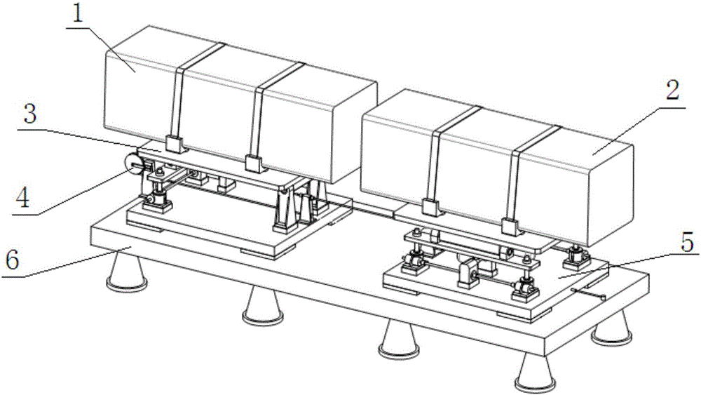
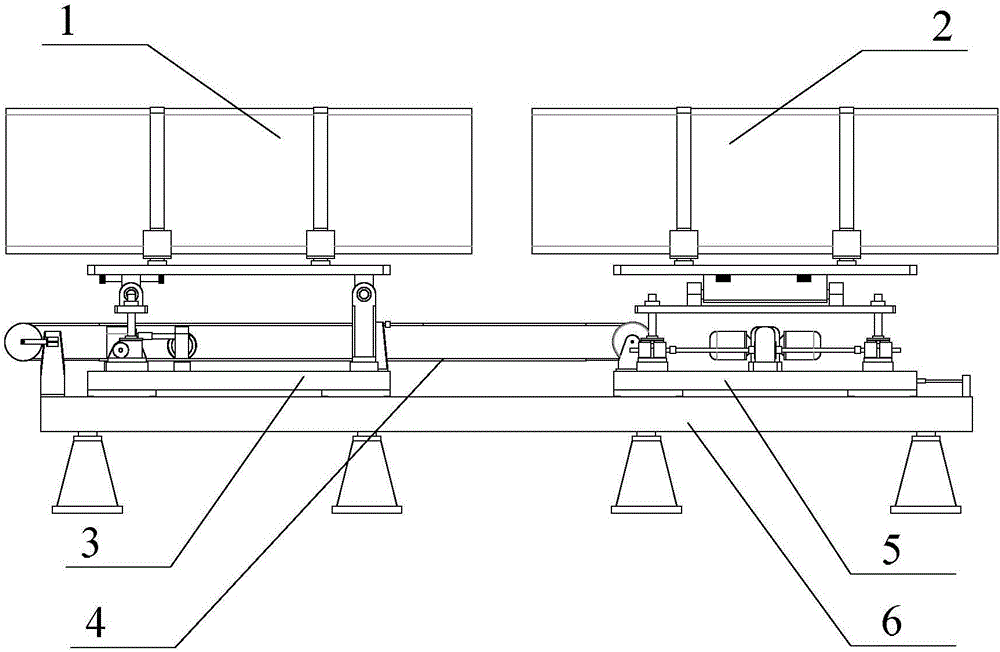
[0005] In order to solve the problems of poor flexibility adaptability, complex mechanism and poor docking compliance in the existing docking assembly platform, the present invention further proposes an air-floating flexible traction docking assembly platform

Method used


Image

  • Air-floating-type flexible pulling butt joint assembling platform
  • Air-floating-type flexible pulling butt joint assembling platform
  • Air-floating-type flexible pulling butt joint assembling platform

Examples


specific Embodiment approach 1

[0015] Specific implementation mode one: combine Figure 1 to Figure 5 Describe this embodiment, an air-floating flexible traction and docking assembly platform described in this embodiment includes a front docking traction bracket 3, a rear docking traction bracket 5, a flexible traction mechanism 4 and an air flotation platform 6, and the front docking traction bracket 3 It is arranged at the lower end of the first docking assembly 1, the rear docking traction bracket 5 is arranged at the lower end of the second docking assembly 2, and the front docking traction bracket 3 and the rear docking traction bracket 5 are arranged on the air bearing platform 6 along the length direction. On the end face, one end of the flexible traction mechanism 4 is arranged on the upper end surface of the air bearing platform 6, the other end of the flexible traction mechanism 4 is arranged on the rear docking traction bracket 5, and the front docking traction bracket 3 realizes the first docking...

specific Embodiment approach 2

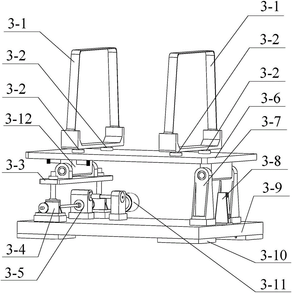
[0019] Specific implementation mode two: combination Figure 1 to Figure 3 Describe this embodiment, the front docking traction bracket 3 described in this embodiment includes a front lifting platform 3-3, a pitching platform 3-6, a support mechanism 3-7, a front floating platform 3-9, a front motor 3-11, a front Slide block 3-12, two front brackets 3-1, two front elevators 3-4 and four front air feet 3-10, four corners of the front floating platform 3-9 lower end face are respectively provided with a front Air feet 3-10, two front elevators 3-4 are arranged on one side of the upper end surface length direction of the front floating platform 3-9, and the two front elevators 3-4 are arranged along the width direction of the front floating platform 3-9. Lift 3-4 is connected with front motor 3-11, and the upper end of two front lifts 3-4 is fixedly connected with front lifting platform 3-3, and the upper end face of front lifting platform 3-3 is along the width direction of floa...

specific Embodiment approach 3

[0030] Specific implementation mode three: combination Figure 1 to Figure 3 To illustrate this embodiment, the front docking traction bracket 3 in this embodiment further includes a front reducer 3-5, and the front motor 3-11 is connected to the front elevator 3-4 through the front reducer 3-5. Other compositions and connection methods are the same as those in the second embodiment.


PUM


Abstract

The invention provides an air-floating-type flexible pulling butt joint assembling platform, relates to the technical field of flexible assembling and aims at solving the problems that an existing butt joint assembling platform is poor in flexibility adaptability, complex in mechanism and poor in butt joint flexible degree. The air-floating-type flexible pulling butt joint assembling platform comprises a front butt joint pulling bracket, a rear butt joint pulling bracket, a flexible pulling mechanism and an air floating platform, wherein the front butt joint pulling bracket and the rear butt joint pulling bracket are arranged on the upper end face of the air floating platform along the length direction, one end of the flexible pulling mechanism is arranged on the upper end face of the air floating platform, the other end of the flexible pulling mechanism is arranged on the rear butt joint pulling bracket, the front butt joint pulling bracket realizes adjustment on a pitch angle of a first butt joint component, the rear butt joint pulling bracket realizes adjustment on a rolling angle and height of a second butt joint component, and the flexible pulling mechanism realizes pulling butt joint between the first butt joint component and the second butt joint component. The air-floating-type flexible pulling butt joint assembling platform is used for flexible butt joint assembling of a product.

Description

technical field [0001] The invention relates to the technical field of flexible assembly, in particular to an air-floating flexible traction docking assembly platform. Background technique [0002] Flexible assembly technology is crucial in the manufacture of cutting-edge equipment. In the field of manufacturing of cutting-edge equipment, there is a class of mechanical products that contain two heavy components. An important process in the assembly process of such products is the butt joint between components. Obviously, the direct docking of two components manually by the operator is only applicable to the case of light components, and for heavy components, only the supporting docking traction platform for product production can be relied on. At present, the docking assembly platform is mainly a mechanical docking platform. The docking traction mechanism and pose adjustment mechanism of this type of platform use mechanical bearings as the core mechanism, which has problems...

Claims


Application Information

Patent Timeline
Patent Type & Authority Applications(China)
IPC IPC(8): B23P19/00
CPCB23P19/00
Inventor 齐乃明姚蔚然霍明英倪阳咏赵钧刘延芳曹世磊刘永孛
Owner HARBIN INST OF TECH
Learn More