
Neurophysiological apparatus and procedures

a technology of neurophysiological apparatus and procedures, applied in the field of neurophysiological techniques, can solve the problems of false negative values, misplaced pedicle screws, injury to nerves and blood vessels surrounding vertebrae, etc., and achieve the effect of improving neurophysiological techniques and preventing nerve damag

Active Publication Date: 2015-09-15
NUVASIVE
View PDF185 Cites 18 Cited by
  • Summary
  • Abstract
  • Description
  • Claims
  • Application Information

AI Technical Summary

Benefits of technology

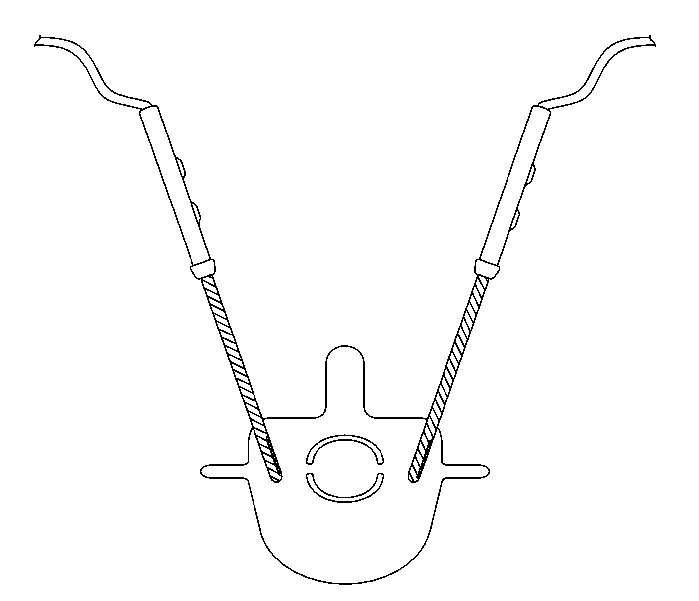
This invention improves neurological techniques by adding a few enhancement features. One feature is the ability to stimulate an instrument while it is advancing into the spine or elsewhere to alert the surgeon if the instrument is too close to a nerve, preventing damage. Another feature is a directional probe that helps surgeons determine the location of the hole in the pedicle, which can aid in avoiding misdirection. Additionally, insulation sleeves are provided to prevent shunting into the soft tissues. A clip is also described that allows for continuous monitoring during spinal procedures, enabling early detection of a breach in the pedicle wall and potentially preventing nerve injury.

Problems solved by technology

Misplaced pedicle screws can injury the nerves and blood vessels that surround the vertebrae.
First, existing systems rely on the conductivity through a patient's body from the pedicle screw to electrodes in extremities or electrodes on the skin of the extremities.
False negative values, low conductivity, can occur if the nerves or the skin do not conduct electricity well.
Damaged nerves can be relatively poor conductors of electricity.
Second, electrical impulses of relatively high magnitudes must be used to overcome the resistance of the skin, muscles, and nerves.
Stimulation by electrical impulses of large amplitude can damage nerves.
For one, the system does not yield real-time data.
Nor does the system allow for efficient, repeated stimulation of instruments that are turned.
In addition, while the system helps surgeons identify holes in the pedicle, it does not identify the location of the hole in the pedicle.
Shunting of electricity can lead to false recordings in the legs or arms (during stimulation in the cervical spine).

Method used


Image

  • Neurophysiological apparatus and procedures
  • Neurophysiological apparatus and procedures
  • Neurophysiological apparatus and procedures

Examples


Embodiment Construction

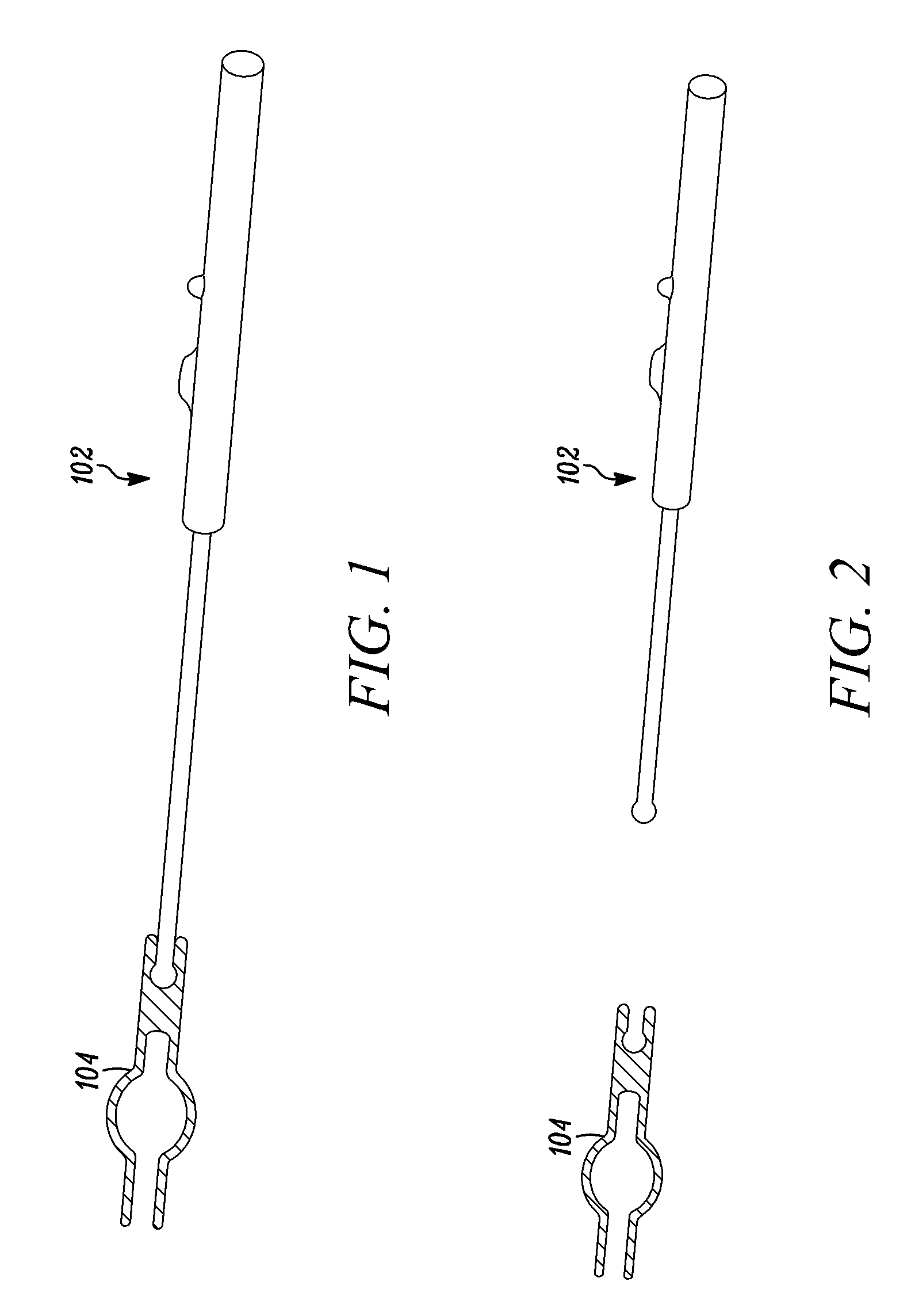
[0080]FIG. 1 is a lateral view of the side of the current probe 102 and a novel clip 104 according to this invention. One end of the clip snaps around instruments. The second end of the clip snaps over the tip of the probe. Alternatively, a second probe tip could be manufactured that incorporates the novel tip end. FIG. 2 is a detached view of the probe and tip of FIG. 1.

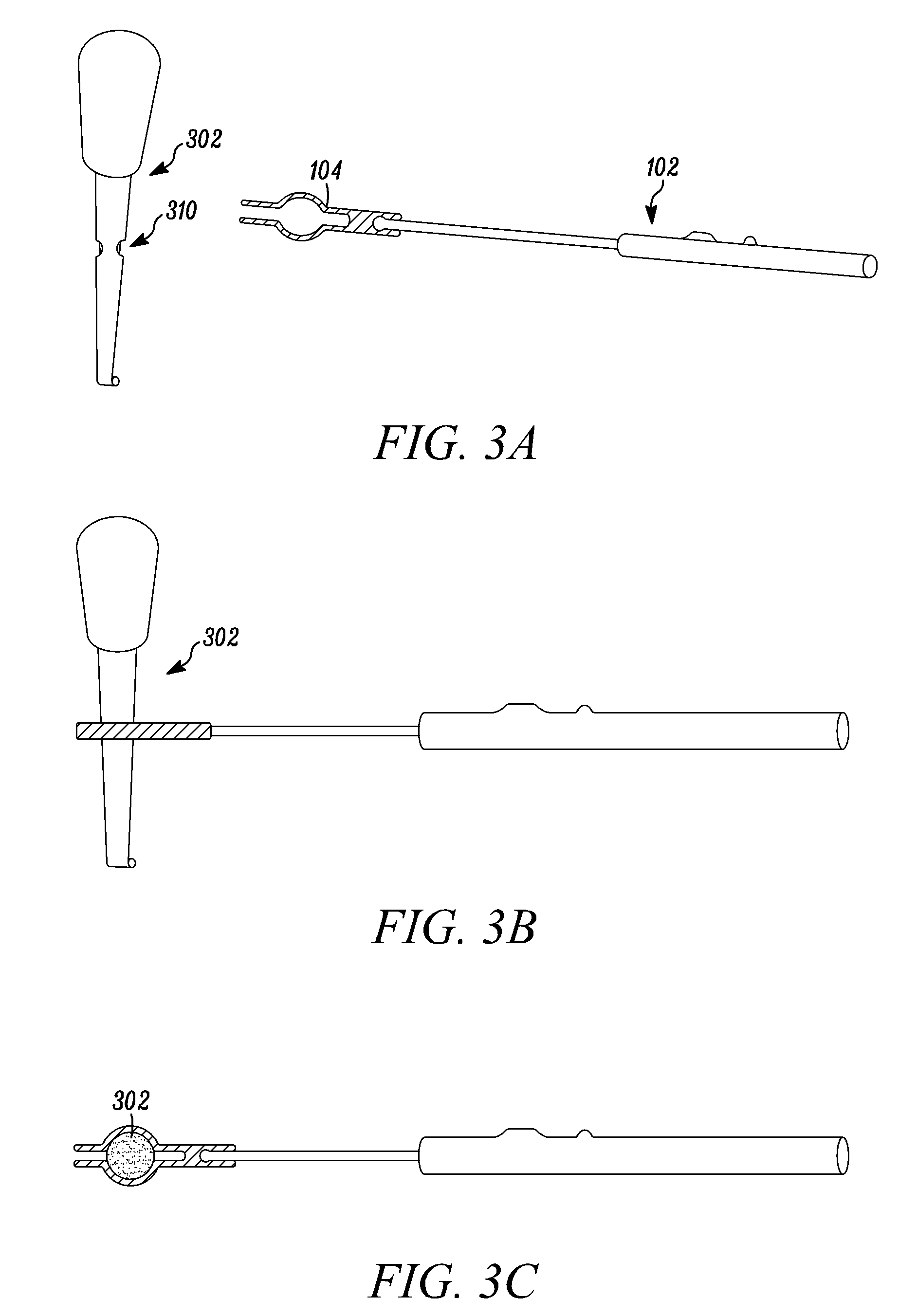
[0081]FIG. 3A is a lateral view of a curette 302 used to “sound” the pedicle and the probe 102 with a clip attachment 104. The shaft of the instrument 302 may be machined with a groove 310 to cooperate with the clip. FIG. 3B is a lateral view of the probe of FIG. 1 attached to the curette of FIG. 3A. FIG. 3C is a cross section.

[0082]FIG. 4 is a lateral view of an alternative embodiment, wherein the shaft of the 20 tap has a raised portion 402 to cooperate with a clip 404. The raised portion 402 avoids the stress riser created by a groove in the shaft. FIG. 5 is a lateral view of the embodiment of the instrument draw...


PUM


Abstract

Neurophysiological instruments and techniques are improved through various enhancements. Stimulation of an instrument is possible while it is advancing into the spine or elsewhere, alerting the surgeon to the first sign the instrument or device (screw) may be too near a nerve. A directional probe helps surgeons determine the location of the hole in the pedicle. Electrically insulating sleeves prevent shunting into the soft tissues. According to a different improvement, the same probe to be used to stimulate different devices, such as screws and wires. Electrical impulses may be recorded from non-muscle regions of the body, including the spine and other portions of the central nervous system as opposed to just the extremities.

Description

CROSS-REFERENCE TO RELATED APPLICATIONS[0001]The present application claims priority under 35 U.S.C. §120 from the commonly owned U.S. patent application Ser. No. 10 / 842,192 filed May 10, 2004, now abandoned, which claims the benefit under 35 U.S.C. §119(e) from U.S. Provisional Application Ser. Nos. 60 / 468,981 filed May 8, 2003, and 60 / 530,427, filed Dec. 17, 2003, the entire contents of which are hereby expressly incorporated by reference into this disclosure as if set forth fully herein.FIELD OF THE INVENTION[0002]This invention relates to neurophysiological techniques and, in particular, to improved instruments and procedures to ensure accurate, real-time, temporary or permanent placement of surgically implanted devices.BACKGROUND OF THE INVENTION[0003]Pedicle instrumentation is often used to facilitate spinal fusion. Pedicle screws extend through the pedicles of vertebrae and into the body of the vertebrae. The screws are connected by rods or plates to eliminate motion between ...

Claims


Application Information

Patent Timeline
Patent Type & Authority Patents(United States)
IPC IPC(8): A61B17/70A61B17/16A61N1/08
CPCA61B17/1671A61B17/1626A61N1/08A61B5/388A61B5/395A61B5/4566A61B5/4893A61B17/7092A61B2017/00039
Inventor FERREE, BRET A.
Owner NUVASIVE
Learn More