
Organic light emitting display device and display panel thereof

a technology of light-emitting display device and display panel, which is applied in the direction of static indicating device, electroluminescent light source, instruments, etc., can solve the problems of affecting the image quality, and affecting the performance of the display panel

Active Publication Date: 2015-09-01
LG DISPLAY CO LTD
View PDF33 Cites 6 Cited by
  • Summary
  • Abstract
  • Description
  • Claims
  • Application Information

AI Technical Summary

Benefits of technology

The present invention provides an organic light emitting display device and a display panel that can continuously maintain a threshold voltage of a driving transistor within a range of compensation for the threshold voltage, even if the threshold voltage of the driving transistor is deviated and shifted from the range of the compensation as the driving time of the driving transistor increases. This enables the display device to perform a recovery driving for the recovery of a threshold voltage shift and ensures a stable display output.

Problems solved by technology

In this case, luminance of the corresponding pixel may not be achieved at a desired level, and / or a luminance difference between pixels may occur, thereby degrading the image quality.
However, with this threshold voltage compensation technology, there is a problem in that compensation for the threshold voltage of the driving transistor can be established only within a predetermined range.
That is, when the threshold voltage of the driving transistor increases above a specific value, or decreases below a specific value, there is a problem in that the threshold voltage compensation technology has a compensation limit in which the varied threshold voltage cannot be compensated for.
Therefore, there is a problem in that the pixel compensation technology may not be able to adequately compensate for the threshold voltage, thereby causing the quality of an image to degrade, and the driving transistor to be incapable of being driven for a long time.

Method used


Image

  • Organic light emitting display device and display panel thereof
  • Organic light emitting display device and display panel thereof
  • Organic light emitting display device and display panel thereof

Examples


Embodiment Construction

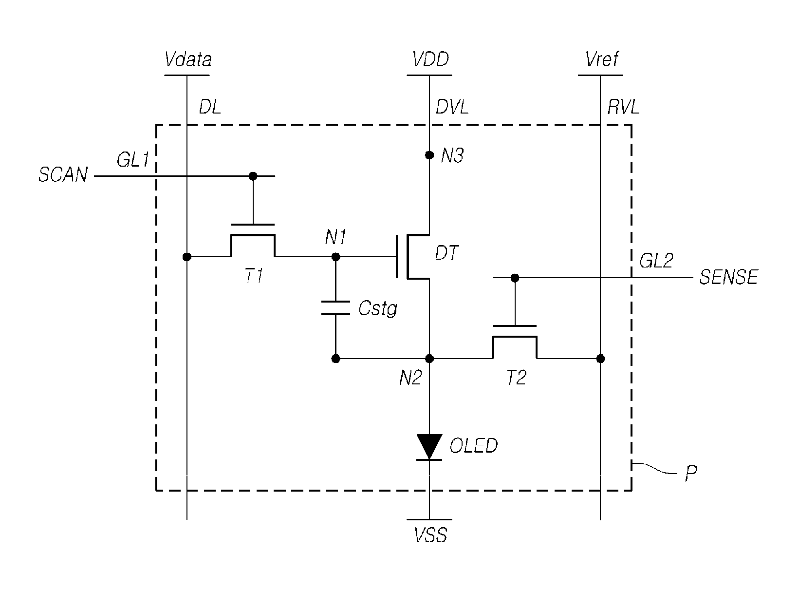
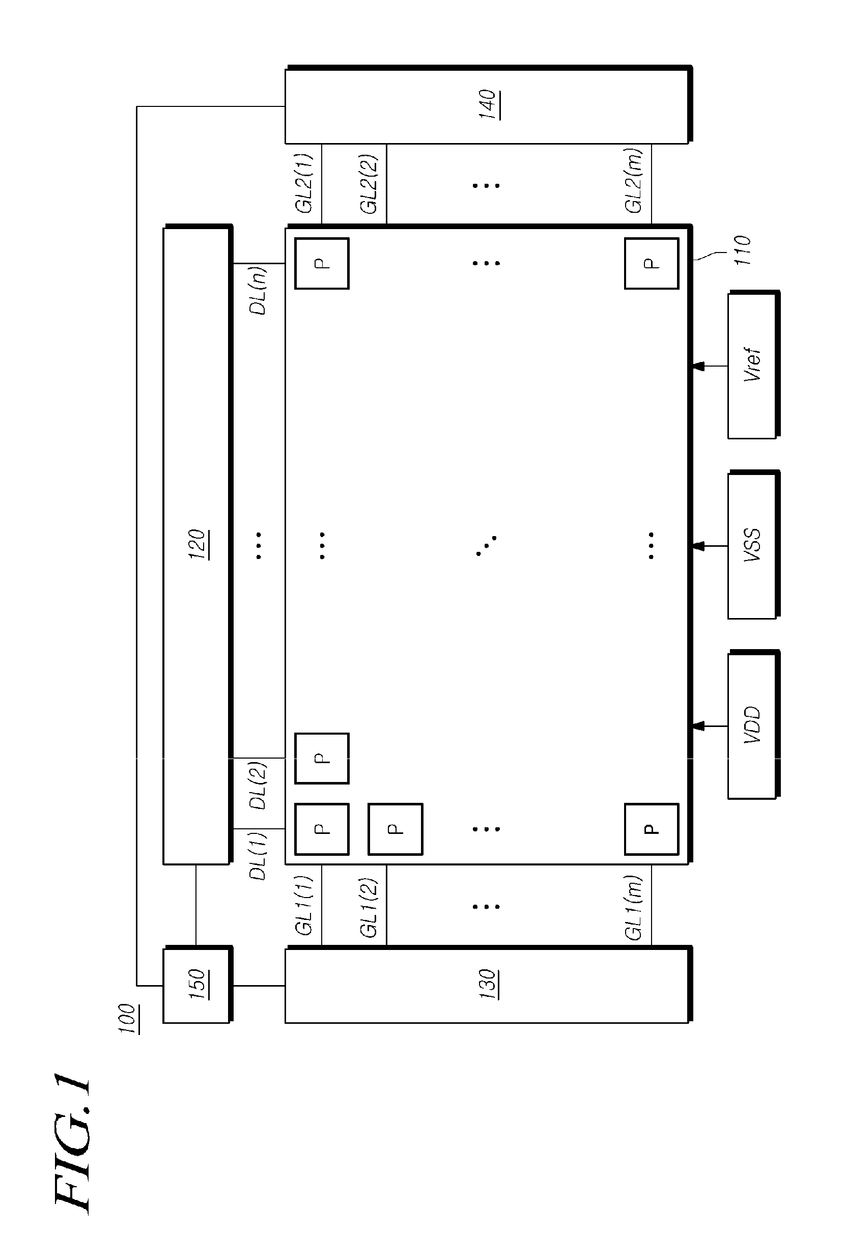
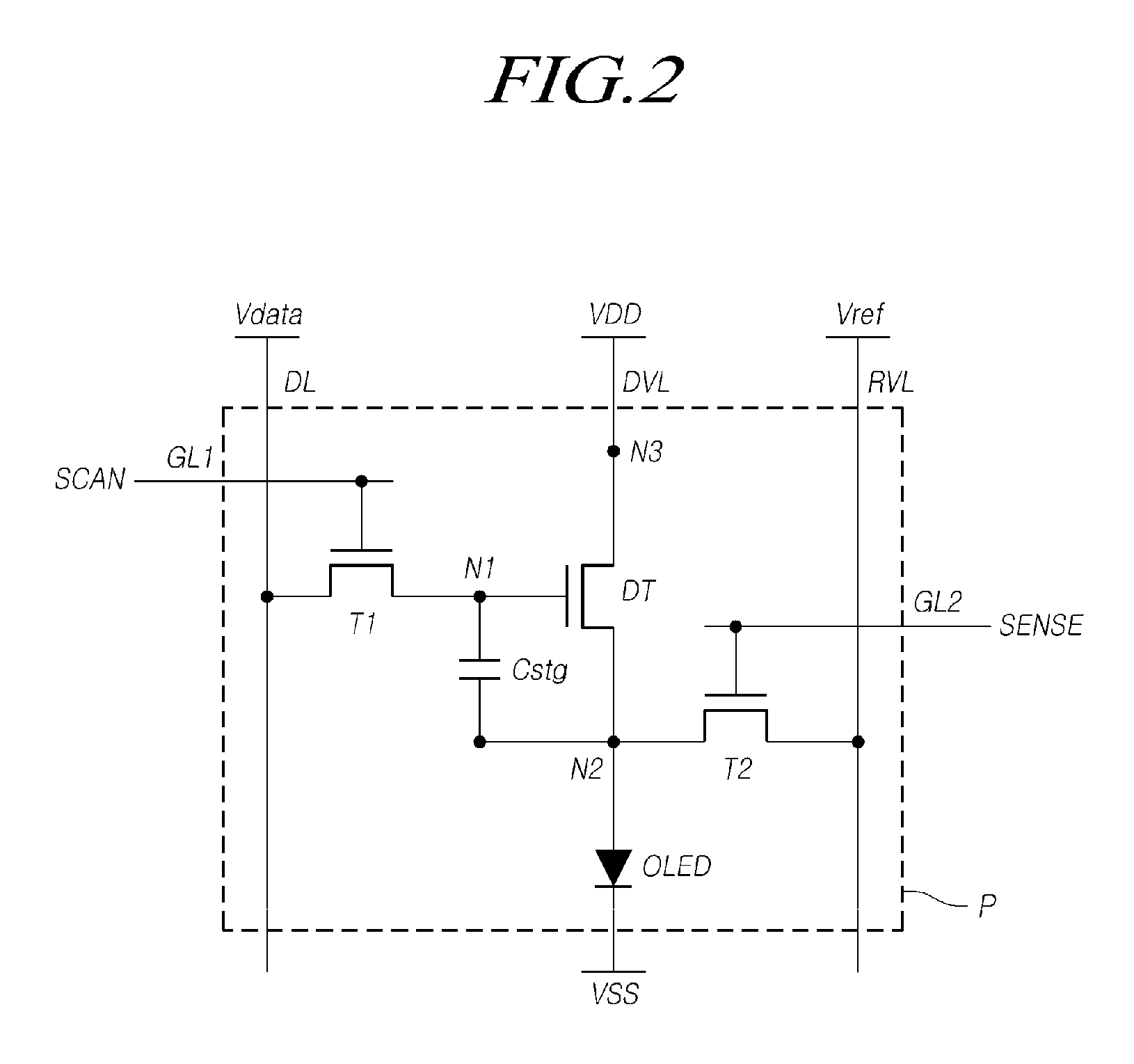
[0031]Hereinafter, example embodiments of the present invention will be described with reference to the accompanying drawings. In the following description, the same or similar elements may be designated by the same or similar reference numerals, although they are shown in different drawings. Further, in the following description, detailed descriptions of known functions and configurations incorporated herein may be omitted when, for example, it may make the subject matter of embodiments of the present invention unclear or confusing.

[0032]In addition, terms such as first, second, A, B, (a), (b) or the like, may be used herein when describing components of embodiments of the present invention. Terminologies such as these may not used to define an essence, order sequence, or number of a corresponding component, but may be used merely to distinguish the corresponding component from other component(s). If it is described in the specification that one component is “connected,”“coupled,” ...


PUM


Abstract

Disclosed are an organic light emitting display device and a display panel thereof, which are capable of performing a recovery driving for recovering a threshold voltage of a driving transistor to be within a range of compensation for the threshold voltage if the threshold voltage of the driving transistor deviates from the range of the compensation for the threshold voltage as a driving time of the driving transistor of a pixel increases.

Description

CROSS-REFERENCE TO RELATED APPLICATIONS[0001]This application claims priority from and the benefit wider 35 U.S.C. §119(a) of Korean Patent Application No. 10-2013-0143561, filed on Nov. 25, 2013, which is hereby incorporated by reference for all purposes as if fully set forth herein.BACKGROUND[0002]1. Field of the Invention[0003]Embodiments of the present invention relate to an organic light emitting display device and a display panel thereof.[0004]2. Description of Related Art[0005]Recently, an organic light emitting display device has come into the spotlight. Organic light emitting display devices may have advantages such as a fast response rate, high light emitting efficiency, high luminance, and a wide viewing angle. These advantages may be attributable to the use of an organic light emitting diode, which emits light by itself.[0006]In such an organic light emitting display device, pixels including organic light emitting diodes respectively are arranged and brightness of select...

Claims


Application Information

Patent Timeline
Patent Type & Authority Patents(United States)
IPC IPC(8): G09G3/32H05B44/00
CPCG09G3/3233G09G2300/08G09G2310/0256G09G2310/061G09G2300/0819G09G2300/0842G09G2320/0295G09G2320/045G09G2330/027G09G3/2092G09G2320/0693
Inventor NAM, WOOJINSHIN, HONGJAE
Owner LG DISPLAY CO LTD
Learn More