Programmable logic device
a logic device and programmable technology, applied in logic circuits, logic circuit coupling/interface arrangements, pulse techniques, etc., can solve the problems of complex control logic and difficulty in fine-grained multi-context pld to precisely control power
- Summary
- Abstract
- Description
- Claims
- Application Information
AI Technical Summary
Benefits of technology
Problems solved by technology
Method used
Image
Examples
embodiment 1
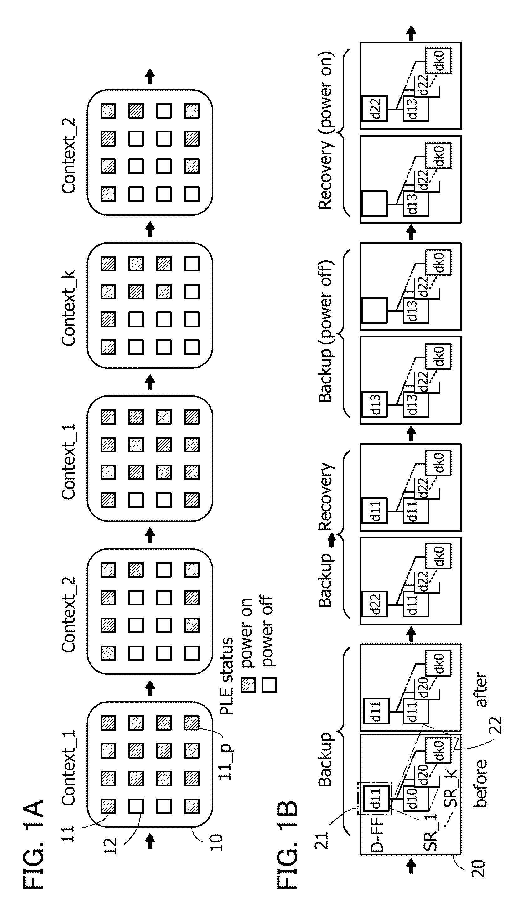
[0064]In this embodiment, PLD structures are described. FIGS. 1A and 1B are schematic diagrams illustrating PLD structures and PLD function effects.
[0065]A PLD 10 in FIG. 1A includes a plurality of programmable logic elements. FIG. 1A illustrates programmable logic elements by blocks. The programmable logic element can control power supply in each unit block. In FIG. 1A, a state in which power is supplied to programmable logic elements 11 represented by oblique hatching, i.e., a power-on state, and a state in which supply of power to programmable logic elements 12 is stopped, i.e., a power-off state are illustrated.
[0066]For example, FIG. 1A illustrates a state in which by switching first to k-th context signals (k is a natural number of 2 or more), a circuit structure is changed from a circuit structure using a first context (context—1) to a circuit structure using a second context (context—2), the circuit structure using the first context (context—1), a circuit structure using a k...
embodiment 2
[0095]In this embodiment, a circuit structure example of a PLD, a circuit structure example of a programmable logic element, and a circuit structure example of each circuit included in the programmable logic element are described.
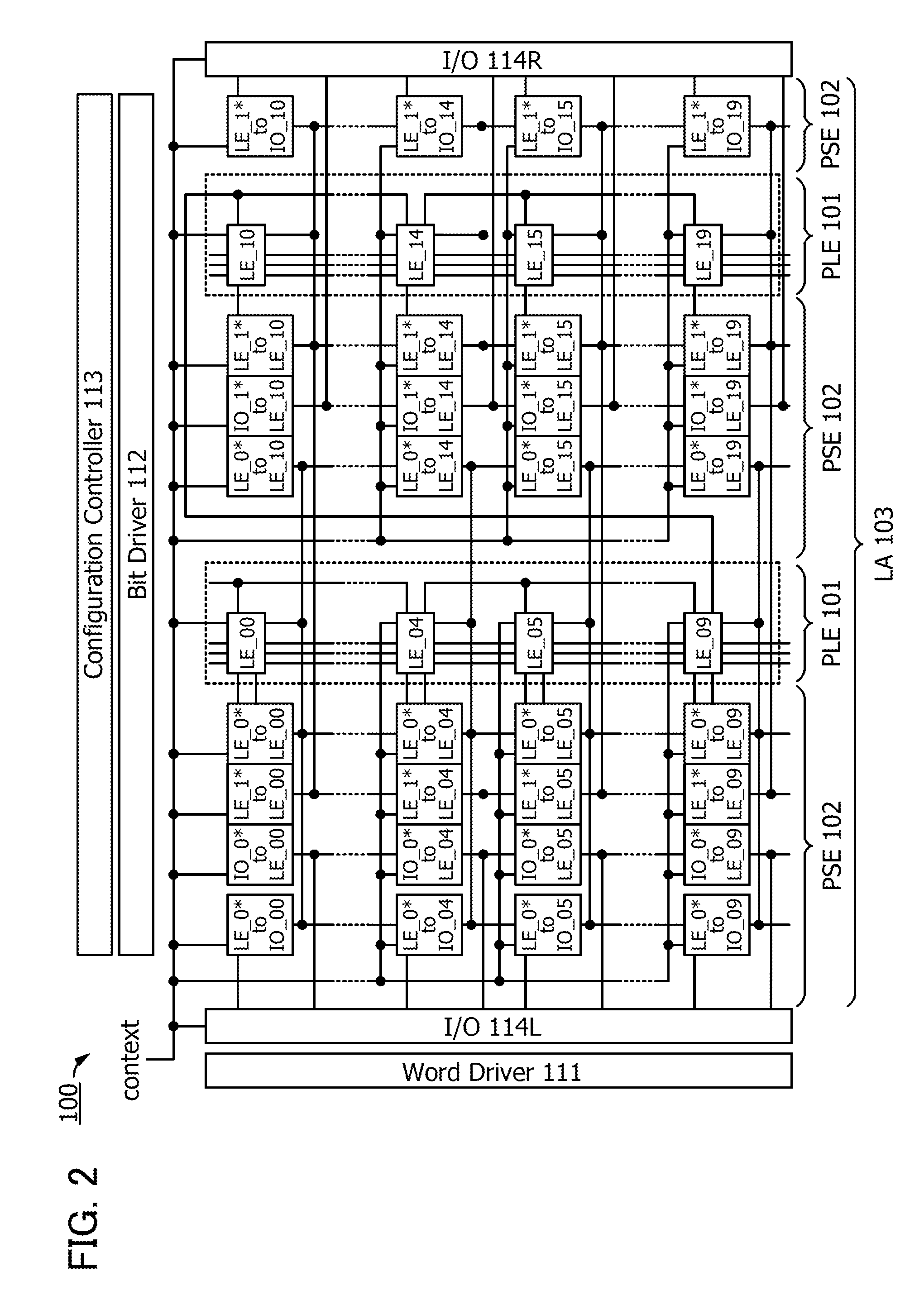
[0096]A structure example of a PLD is described. Part of the structure of a PLD 100 is illustrated in FIG. 2.
[0097]As the structure of the PLD 100, FIG. 2 illustrates a block diagram in which a logic array 103 (abbreviated to LA) including programmable logic elements 101 (abbreviated to PLE) and programmable switch elements 102 (abbreviated to PSE), a word line driver circuit 111 (Word Driver), a bit line driver circuit 112 (Bit Driver), a configuration control circuit 113 (Configuration Controller), an input / output terminal portion 114L (I / O), and an input / output terminal portion 114R (I / O) are provided.
[0098]FIG. 2 illustrates an example in which the programmable logic elements 101 and the programmable switch elements 102 are arranged in a column directio...
embodiment 3
[0183]In this embodiment, an oxide semiconductor layer that can be used as the semiconductor layer of the transistor with low off-state current described in the above embodiment is described.
[0184]An oxide semiconductor used for a channel formation region in the semiconductor layer of the transistor preferably contains at least indium (In) or zinc (Zn). In particular, In and Zn are preferably contained. A stabilizer for strongly bonding oxygen is preferably contained in addition to In and Zn. As a stabilizer, at least one of gallium (Ga), tin (Sn), zirconium (Zr), hafnium (Hf), and aluminum (Al) may be contained.
[0185]As another stabilizer, one or more kinds of lanthanoid such as lanthanum (La), cerium (Ce), praseodymium (Pr), neodymium (Nd), samarium (Sm), europium (Eu), gadolinium (Gd), terbium (Tb), dysprosium (Dy), holmium (Ho), erbium (Er), thulium (Tm), ytterbium (Yb), and lutetium (Lu) may be contained.
[0186]As the oxide semiconductor used for the semiconductor layer of the t...
PUM
 Abstract
Description
Claims
Application Information
 - R&D
- Intellectual Property
- Life Sciences
- Materials
- Tech Scout
- Unparalleled Data Quality
- Higher Quality Content
- 60% Fewer Hallucinations
Browse by: Latest US Patents, China's latest patents, Technical Efficacy Thesaurus, Application Domain, Technology Topic, Popular Technical Reports.
© 2025 PatSnap. All rights reserved.Legal|Privacy policy|Modern Slavery Act Transparency Statement|Sitemap|About US| Contact US: help@patsnap.com


