Image forming device and method for controlling a power supply for transfer

a technology of image forming and power supply, which is applied in the direction of instruments, electrographic process equipment, optics, etc., can solve the problems of deteriorating image formation, delay in high voltage transfer, image noise on image carriers, etc., and achieve the effect of free of the risk of unallowable discharg

Active Publication Date: 2015-06-16
KONICA MINOLTA BUSINESS TECH INC
View PDF17 Cites 0 Cited by
  • Summary
  • Abstract
  • Description
  • Claims
  • Application Information

AI Technical Summary

Benefits of technology

[0030]the power supply for transfer being turned on by a power supply ON instruction signal, being turned off by a power supply OFF instruction signal, and using a voltage set by an output voltage setting signal as an output voltage when it is on, the image forming device being free of the risk of unallowable discharge by a high voltage for transfer applied from the power supply for transfer to the transfer member for transferring the toner image onto the recording paper sheet by the transfer member and a delay in the rise of the high voltage for transfer, and being successfully capable of transferring the toner image on the image carrier onto the recording paper sheet.
[0036]the power supply for transfer being turned on by a power supply ON instruction signal, being turned off by a power supply OFF instruction signal, and using a voltage set by an output voltage setting signal as an output voltage when it is on, the method being free of the risk of unallowable discharge by a high voltage for transfer applied from the power supply for transfer to the transfer member for transferring the toner image onto the recording paper sheet by the transfer member and a delay in the rise of the high voltage for transfer, and being successfully capable of transferring the toner image on the image carrier onto the recording paper sheet.

Problems solved by technology

As for the transfer member, if it is pressed against the image carrier at all times, it may be deformed due to creep deformation or other causes when the image forming device is not used for a long period of time or in other situations, and the deformation may lead to deteriorated image formation.
In the image forming device in which the transfer member which is capable of pressing against, coming into contact with and retreating from the image carrier by the contact-retreat drive unit is employed, in pressing the transfer member for transferring the toner image on the image carrier onto the recording paper sheet against the image carrier, when the transfer member is pressed against the image carrier in a state that a high voltage for transfer is applied to the transfer member, unallowable discharge may occur between the transfer member and the image carrier, leading to the phenomenon known as memory causing an image noise on the image carrier.
As a result, if the distance from the front end of the recording paper sheet which is being paused normally by the timing roller unit to the pressing nip between the image carrier and the transfer member is set shorter to achieve size reduction and compactness of the image forming device and for other reasons, the rise of the high voltage for transfer is delayed with respect to the entrance of the recording paper sheet into the pressing nip, and considerable transfer failure may occur at an early stage of the transfer of the toner image onto the recording paper sheet.

Method used


Image

  • Image forming device and method for controlling a power supply for transfer
  • Image forming device and method for controlling a power supply for transfer
  • Image forming device and method for controlling a power supply for transfer

Examples


Embodiment Construction

[0059]The image forming device and the method for controlling a power supply for transfer according to the embodiments of the present invention are basically as follows:

(1) Image Forming Device

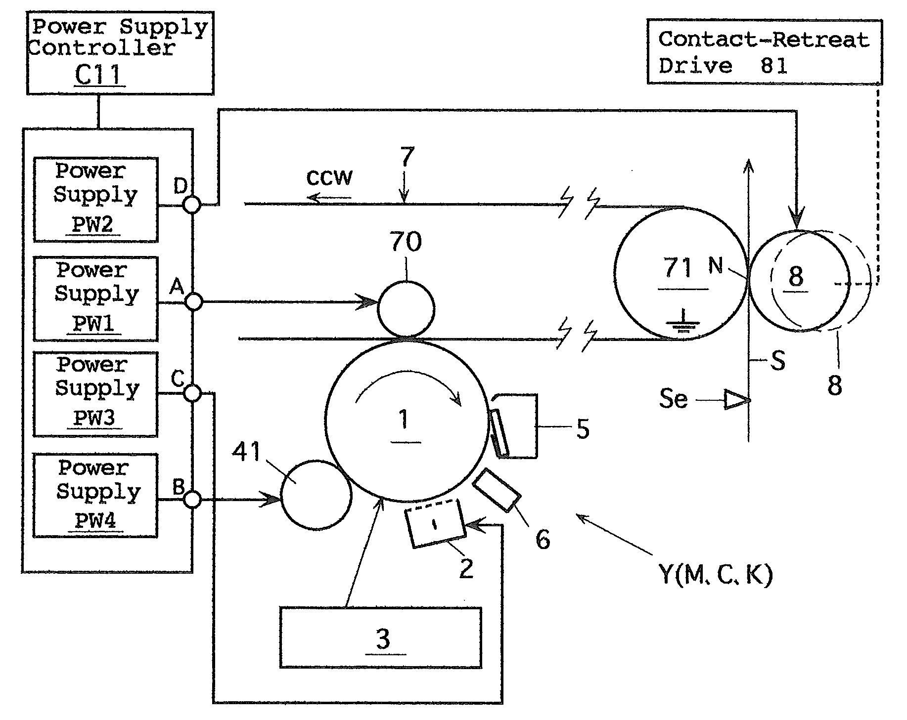
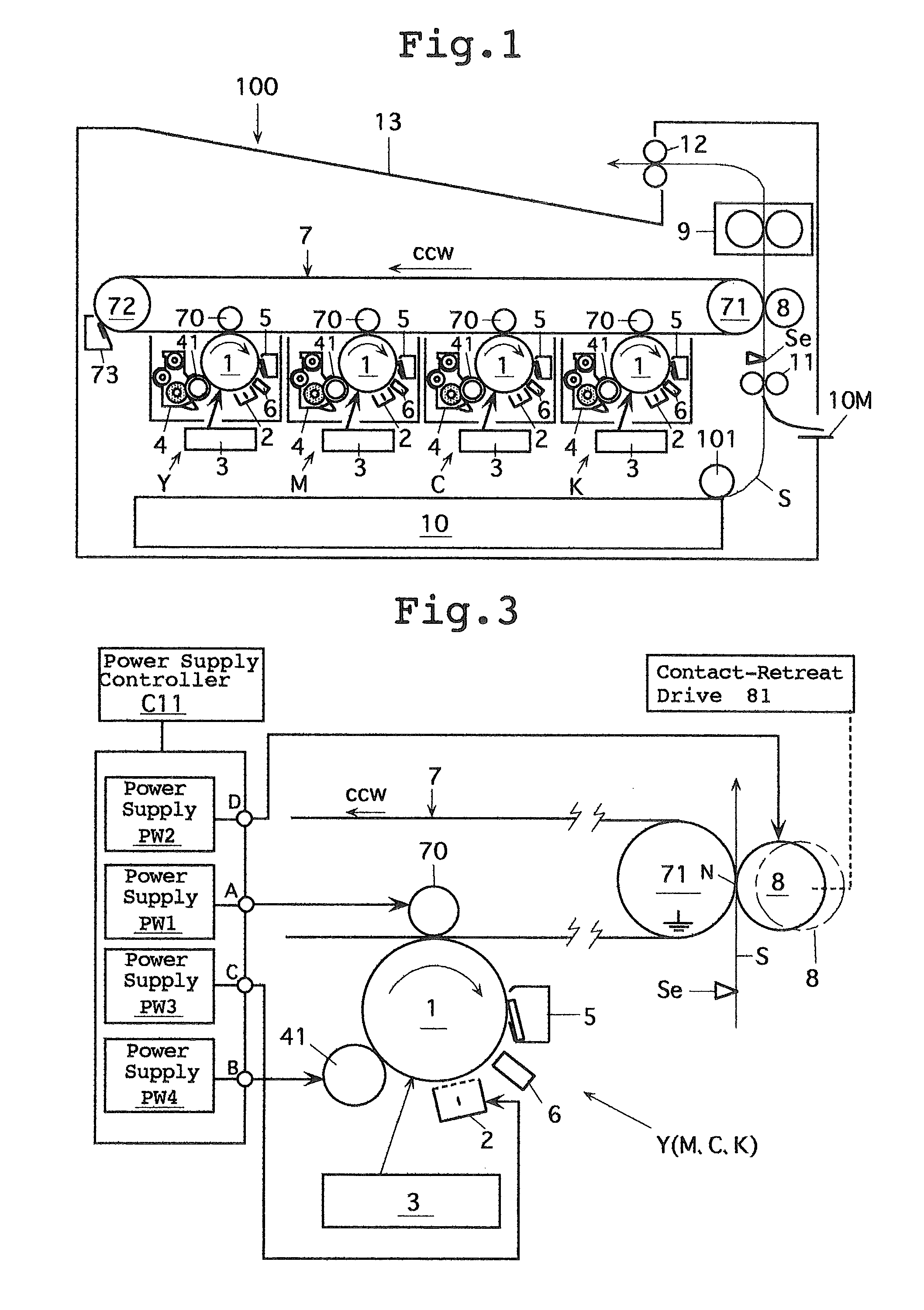
[0060]An image forming device comprising:

[0061]an image carrier which is rotatable and capable of forming a toner image on a circumferential surface thereof, and is capable of rotating while holding the toner image thereon,

[0062]a transfer member which is for transferring the toner image on the image carrier onto a recording paper sheet and capable of rotating, provided in a manner capable of pressing against, coming into contact with and retreating from the image carrier, and which forms a pressing nip by being pressed against the image carrier,

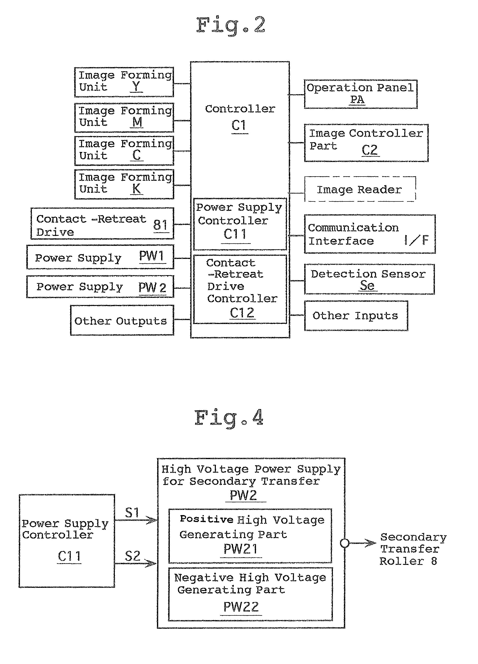
[0063]a power supply for transfer for applying a voltage to the transfer member for transfer for transferring the toner image on the image carrier onto the recording paper sheet, and

[0064]a recording paper sheet feed device for feeding the recording pa...


PUM


Abstract

An image forming device includes a power supply for transfer for applying a voltage for transfer for transferring the toner image on the image carrier onto the recording paper sheet to the transfer member, and a recording paper sheet feed device for feeding the recording paper sheet into the pressing nip, and the method for controlling a power supply for transfer. The power supply for transfer is turned on and the output voltage of the power supply for transfer is set to 0 V before the transfer member is pressed against the image carrier, and the output voltage of the power supply for transfer is switched from 0 V to a high voltage for transfer after the transfer member is pressed against the image carrier.

Description

CROSS-REFERENCE TO RELATED APPLICATION[0001]This invention is based on Japanese patent application No. 2010-99975 filed in Japan on Apr. 23, 2010, the entire content of which is hereby incorporated by reference.BACKGROUND OF THE INVENTION[0002]1. Field of the Invention[0003]The present invention relates to an image forming device such as a copying machine, a printer, a facsimile machine, a multifunctional machine having functions of two or more of these and the like, and further to a method for controlling a power supply for transfer for transferring a toner image in such an image forming device onto a recording sheet such as a recording paper sheet.[0004]2. Description of Related Art[0005]Today, various types of image forming devices are known. Among them, there are such image forming devices which can form a toner image on an image carrier whose surface moves, and transfer the toner image onto a recording paper sheet, a recording sheet for an overhead projector or the like (herein...

Claims


Application Information

Patent Timeline
Patent Type & Authority Patents(United States)
IPC IPC(8): G03G15/16G03G15/00
CPCG03G15/5004G03G15/1675G03G2215/00409G03G2215/00599G03G2215/00603G03G2215/1614
Inventor TANAKA, TAKAFUMIWATANABE, TAKASHI
Owner KONICA MINOLTA BUSINESS TECH INC
Why Eureka
Try Eureka