Vehicle lock-up clutch control device

a clutch control and clutch technology, applied in the direction of clutches, gearing elements, gearing, etc., can solve the problems of engine racing, lock-up capacity not being generated, shock, etc., and achieve the effect of reducing engine torque, reducing engine racing, and delay in lock-up command pressur

Active Publication Date: 2017-06-22
NISSAN MOTOR CO LTD
View PDF0 Cites 0 Cited by
  • Summary
  • Abstract
  • Description
  • Claims
  • Application Information

AI Technical Summary

Benefits of technology

[0007]In view of the problem described above, an object of the present invention is to provide a lock-up clutch control device of a vehicle that is capable of suppressing engine racing when engaging the lock-up clutch at the time of starting to move.
[0009]Therefore, if the source pressure of the actual lock-up oil pressure is rising when the lock-up clutch is engaged at the time of starting to move, a rise in the lock-up command pressure is delayed. Then, a torque reduction in the engine is executed, at least during the delay in the lock-up command pressure. That is, the engine torque is reduced and engine racing is suppressed by executing a torque reduction in the engine during a delay in the lock-up command pressure when a lock-up capacity is not generated. As a result, it is possible to suppress engine racing when the lock-up clutch is engaged at the time of starting to move.

Problems solved by technology

When engaging a lock-up clutch at the time of a vehicle starting to move, the line pressure of the actual lock-up oil pressure is not stabilized while the source pressure (line pressure) of the actual lock-up oil pressure is rising, and the following ability of the actual lock-up oil pressure to the lock-up command pressure is poor, so there is the possibility that shock occurs.
However, in a conventional device, when engaging the lock-up clutch at the time of starting to move, a lock-up capacity is not generated while a constant value is maintained by a command pressure delay.
Consequently, there is the problem that the engine torque becomes excessively large during the lock-up command pressure delay, leading to an occurrence of engine racing.
Therefore, if the source pressure of the actual lock-up oil pressure is rising when the lock-up clutch is engaged at the time of starting to move, a rise in the lock-up command pressure is delayed.

Method used


Image

  • Vehicle lock-up clutch control device
  • Vehicle lock-up clutch control device
  • Vehicle lock-up clutch control device

Examples


first embodiment

[0018]The configuration is described first. The “Overall system configuration” and the “Initial-motion lock-up control configuration” will be separately described regarding the configuration of the lock-up clutch control device for a vehicle in the first embodiment.

Overall System Configuration

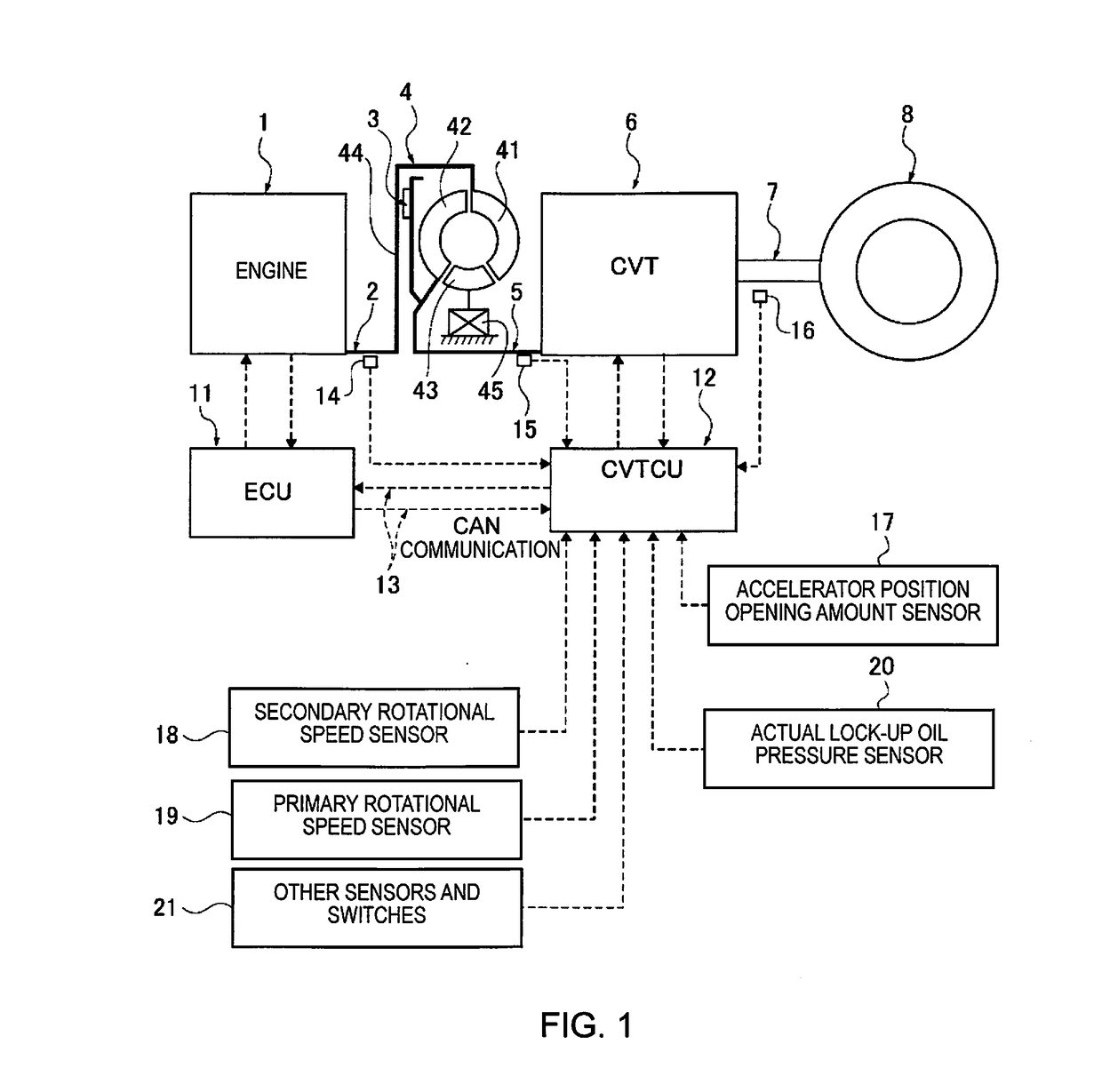
[0019]FIG. 1 illustrates an engine-equipped vehicle to which is applied a lock-up clutch control device of the first embodiment. The overall system configuration will be described below, based on FIG. 1.

[0020]As illustrated in FIG. 1, a vehicle drive system comprises an engine 1, an engine output shaft 2, a lock-up clutch 3, a torque converter 4, a transmission input shaft 5, a continuously variable transmission 6 (transmission), a drive shaft 7 and a drive wheel 8.

[0021]The lock-up clutch 3, built into the torque converter 4, couples the engine 1 and the transmission 6 via the torque converter 4 by releasing the clutch, and directly connects the engine output shaft 2 and the transmission input...

second embodiment

[0058]The second embodiment is an example in which the lock-up capacity generation timing to end the engine torque reduction control is determined by a change rate condition.

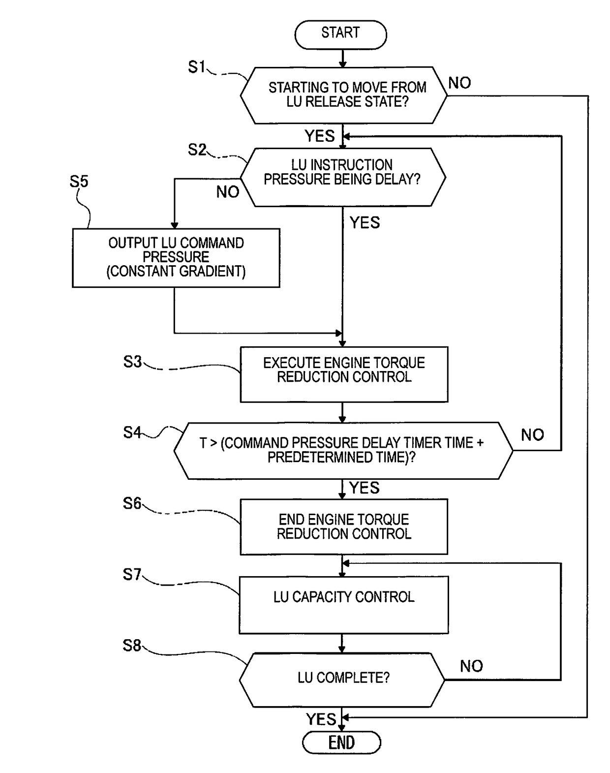
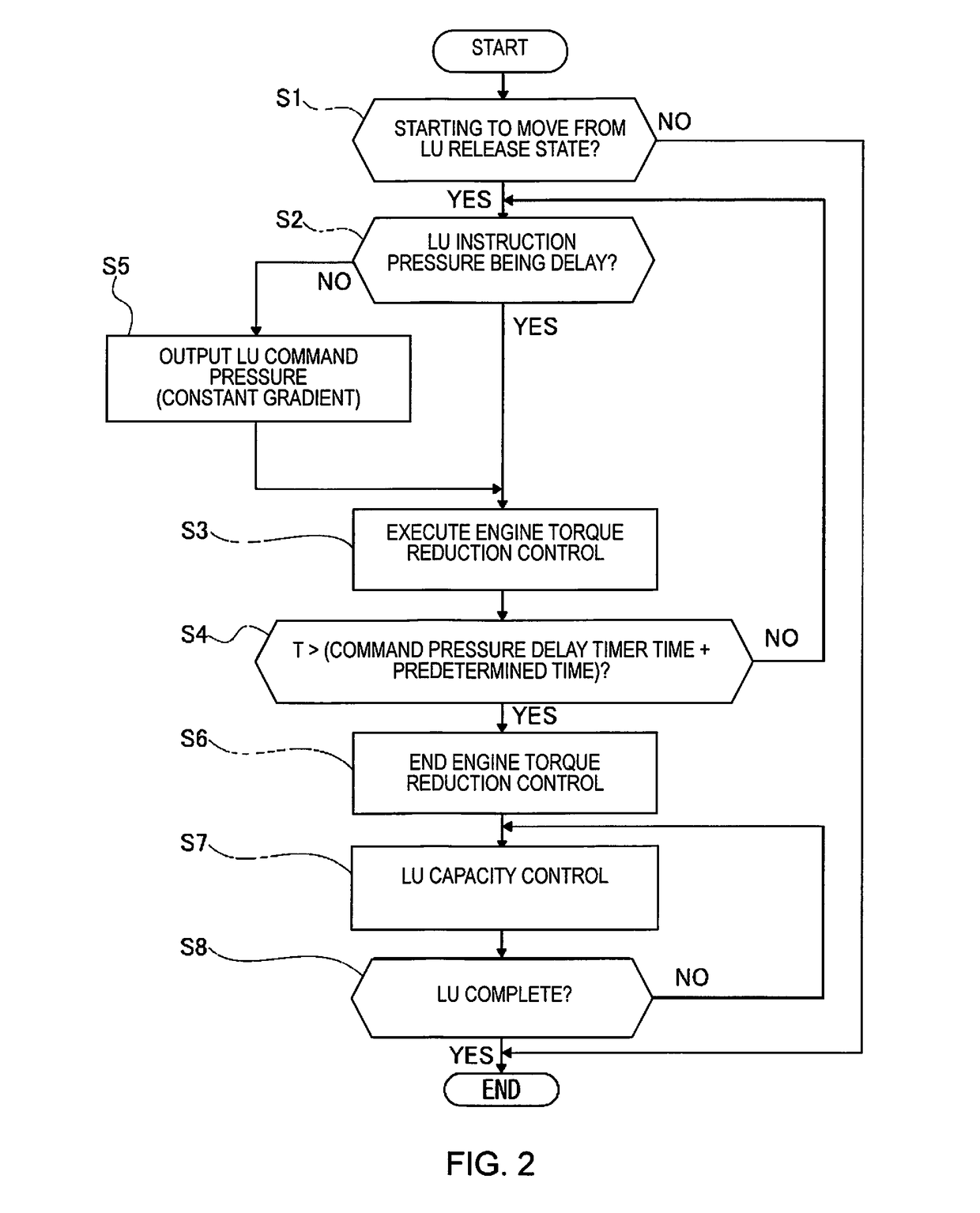
[0059]The configuration is described first. FIG. 6 illustrates the flow of the initial-motion lock-up control process that is executed by the CVT control unit 12 according to the second embodiment (initial-motion lock-up control means). Each step in FIG. 6 showing the configuration of the initial-motion lock-up control process will be described below. Since each of the steps of Step S21-Step S23 and Step S25-Step S28 are steps that carry out the same processes as each of the steps of Step S1-Step S3 and Step S5-Step S8 in FIG. 2, the descriptions thereof are omitted.

[0060]In Step S24, following the execution of the engine torque reduction control in Step S23, it is determined whether or not a change rate condition of either an engine rotational speed change rate being greater than or equal to a predetermined val...

third embodiment

[0064]The third embodiment is an example in which the lock-up capacity generation timing to end the engine torque reduction control is determined by a lock-up pressure condition.

[0065]The configuration is described first. FIG. 7 illustrates the flow of the initial-motion lock-up control process that is executed by the CVT control unit 12 according to the third embodiment (initial-motion lock-up control means). Each step in FIG. 7 showing the configuration of the initial-motion lock-up control process will be described below. Since each of the steps of Step S31-Step S33 and Step S35-Step S38 are steps that carry out the same processes as each of the steps of Step S1-Step S3 and Step S5-Step S8 in FIG. 2, the descriptions thereof are omitted.

[0066]In Step S34, following the execution of the engine torque reduction control in Step S33, it is determined whether or not a lock-up pressure condition of either the lock-up command pressure exceeding a constant value, or the actual lock-up oi...


PUM


Abstract

A vehicle lock-up clutch control device is provided to suppress engine racing when a lock-up clutch is engaged at the time a vehicle starts moving. The vehicle lock-up clutch control device is provided with a control unit that delays the rise in lock-up command pressure if a line pressure, which is the source pressure of the actual lock-up oil pressure, is rising when the lock-up clutch is engaged at the time the vehicle starts moving. The control unit executes a torque reduction in the engine at least during the delay in the lock-up command pressure.

Description

CROSS-REFERENCE TO RELATED APPLICATIONS[0001]This application is a U.S. National stage application of International Application No. PCT / JP2014 / 072744, filed on Aug. 29, 2014.BACKGROUND[0002]Field of the Invention[0003]The present invention relates to a lock-up clutch control device for a vehicle that engages a lock-up clutch of a torque converter at the time of starting to move.[0004]Background Information[0005]When engaging a lock-up clutch at the time of a vehicle starting to move, the line pressure of the actual lock-up oil pressure is not stabilized while the source pressure (line pressure) of the actual lock-up oil pressure is rising, and the following ability of the actual lock-up oil pressure to the lock-up command pressure is poor, so there is the possibility that shock occurs. Accordingly, a device is known in which the lock-up command pressure is delayed (maintains a constant value of the command pressure) when the line pressure is rising (for example refer to the Japanese...

Claims


Application Information

Patent Timeline
Patent Type & Authority Applications(United States)
IPC IPC(8): F16D48/02F16H61/14
CPCF16D48/02B60W10/06B60W10/02F16H61/14F16H2061/145F16H2061/146F16D2500/10412F16D48/06F16D2500/3024F16D2500/30401F16D2500/70458F16D2500/70426
Inventor TOHTA, YUZURU
Owner NISSAN MOTOR CO LTD
Why Eureka
Try Eureka