
Image forming apparatus

a technology of forming apparatus and forming plate, which is applied in the direction of electrographic process apparatus, instruments, developers, etc., can solve the problems of excessive melting of toner, insufficient fixing, and gradation in temperature inside the toner layer, so as to shorten the first print output time, improve the effect of fixing property and good offset resistan

Active Publication Date: 2015-06-09
RICOH KK
View PDF45 Cites 1 Cited by
  • Summary
  • Abstract
  • Description
  • Claims
  • Application Information

AI Technical Summary

Benefits of technology

The present invention is an image forming apparatus that combines a fixing unit and electrostatic image developing toner. It has the advantage of shortening the time it takes to print, overcoming issues with heat during high-speed rotation, and being effective in large-scale production. It also exhibits good offset resistance and glossiness at low fixing temperatures.

Problems solved by technology

However, in this method, the heat roller of the fixing member is in contact under pressure with the toner image having a heated and molten state and thus when the temperature of the heating roller is too high, the toner causes hot offset which is a problem that the toner melts excessively and adheres to the heat roller.
Meanwhile, when the temperature of the heat roller is too law, the toner does not melt sufficiently, leading to gradation in temperature inside the toner layer.
As a result, the boundary temperature between the lowermost surface of the toner layer and the surface of the medium does not reach a temperature enough to melt the toner, so that the toner layer is broken, causing cold offset which is a problem that fixing becomes insufficient.
However, reducing the molecular weight and / or the glass transition temperature of a binder resin makes it easier for the obtained toner to aggregate, so that the toner is degraded in storage stability and causes problems such as blocking.
However, the electrophotographic toner of JP-A No. 04-353866 has a high storage modulus G′(150) at 150° C. and a high peak temperature of the loss modulus, and thus is poor in low-temperature fixing property.
However, even the electrophotographic image developing toner of JP-A No. 09-006051 has too high a storage modulus G′(120) at 120° C. and thus is poor in low-temperature fixing property.
In particular, irregularities on the surface of the fixed image reflect light diffusively, so that the glossiness is degraded and the color developing property is also degraded.
As a result, an amount of heat is insufficient especially at the beginning of continuous printing (i.e., a drop in temperature), which is problematic.
As a result, the belt is the coldest at a portion of the nip which a paper sheet enters, which tend to cause fixing failures.
Particularly in high-speed devices, more severe fixing failures tend to occur since the rotation speed of the belt is high and thus a more amount of heat is released from the belt at the other portions than the nip.
Such a mark may break the belt.
A large mark of kink is reflected on the obtained image, causing image failures.
This configuration has a problem that the heat capacity inside the belt is so large that heat is absorbed by these members and thus heat conversion efficiency is low (which is an obstacle of energy saving).
As seen in SURF fixing, when the belt is rotated distant from a heating body (exothermic body), the belt is cooled due to forced convection, so that heat loss increases to degrade heat conversion efficiency.
This measure is not completely effective and leads to shortening the service life of the apparatus and enlarging it.
Thus, it is not a clever measure.
Also, silicone oil used for increasing releaseability is desirably reduced to the greatest extent possible since it contaminates the interior of the apparatus during double-side printing, and it is more difficult to write letters or something on the printed matter.
The electrophotographic toner of JP-A No. 04-353866 has a high storage modulus G′(150) at 150° C. and a high peak temperature of the loss modulus, and thus is poor in low-temperature fixing property.
Also, even the electrophotographic image developing toner of JP-A No. 09-006051 has too high a storage modulus G′(120) at 120° C. and thus is poor in low-temperature fixing property.
The electrophotographic color toner of JP-A No. 08-179563 has too low a storage modulus G′ at T1+20 [° C.] which is A satisfying the above expression, and thus is poor in offset resistance.
Such a toner tends to move onto the fixing member, and is poor in offset resistance.
As described above, it is a quite difficult problem to attain both desired offset resistance and desired glossiness.

Method used


Image

  • Image forming apparatus
  • Image forming apparatus

Examples


example 1

Synthesis of Organic Particle Emulsion

[0214]A reaction container equipped with a stirring rod and a thermometer was charged with 683 parts of water, 11 parts of sodium salt of sulfuric acid ester of ethylene oxide adduct of methacrylic acid (ELEMINOL RS-30, product of Sanyo Chemical Industries Ltd.), 83 parts of styrene, 83 parts of methacrylic acid, 110 parts of butyl acrylate and 1 part of ammonium persulfate. The resultant mixture was stirred at 400 rpm for 15 min to thereby obtain a white emulsion. The white emulsion was heated to a system temperature of 75° C. and was allowed to react for 5 hours. Then, 30 parts by mass of a 1% by mass aqueous ammonium persulfate solution was added to the reaction mixture, followed by aging at 75° C. for 5 hours, to thereby obtain an aqueous dispersion [particle dispersion liquid 1] of a vinyl resin (a copolymer of styrene-methacrylic acid-butyl acrylate-sodium salt of sulfate ester of methacrylic acid-ethylene oxide adduct). The volume average...

example 2

[0226][Toner 2] was obtained in the same manner as in Example 1 except that the [low-molecular-weight polyester 1] was changed to [low-molecular-weight polyester 2] having a number average molecular weight of 3,200, a weight average molecular weight of 9,500, a Tg of 47° C. and an acid value of 19.0.

example 3

[0227][Toner 3] was obtained in the same manner as in Example 1 except that the [low-molecular-weight polyester 1] was changed to [low-molecular-weight polyester 3] having a number average molecular weight of 4,200, a weight average molecular weight of 8,200, a Tg of 52° C. and an acid value of 18.0 and to [crystalline polyester 2] having a melting point of 89° C. and a SP value of 9.5.


PUM


Abstract

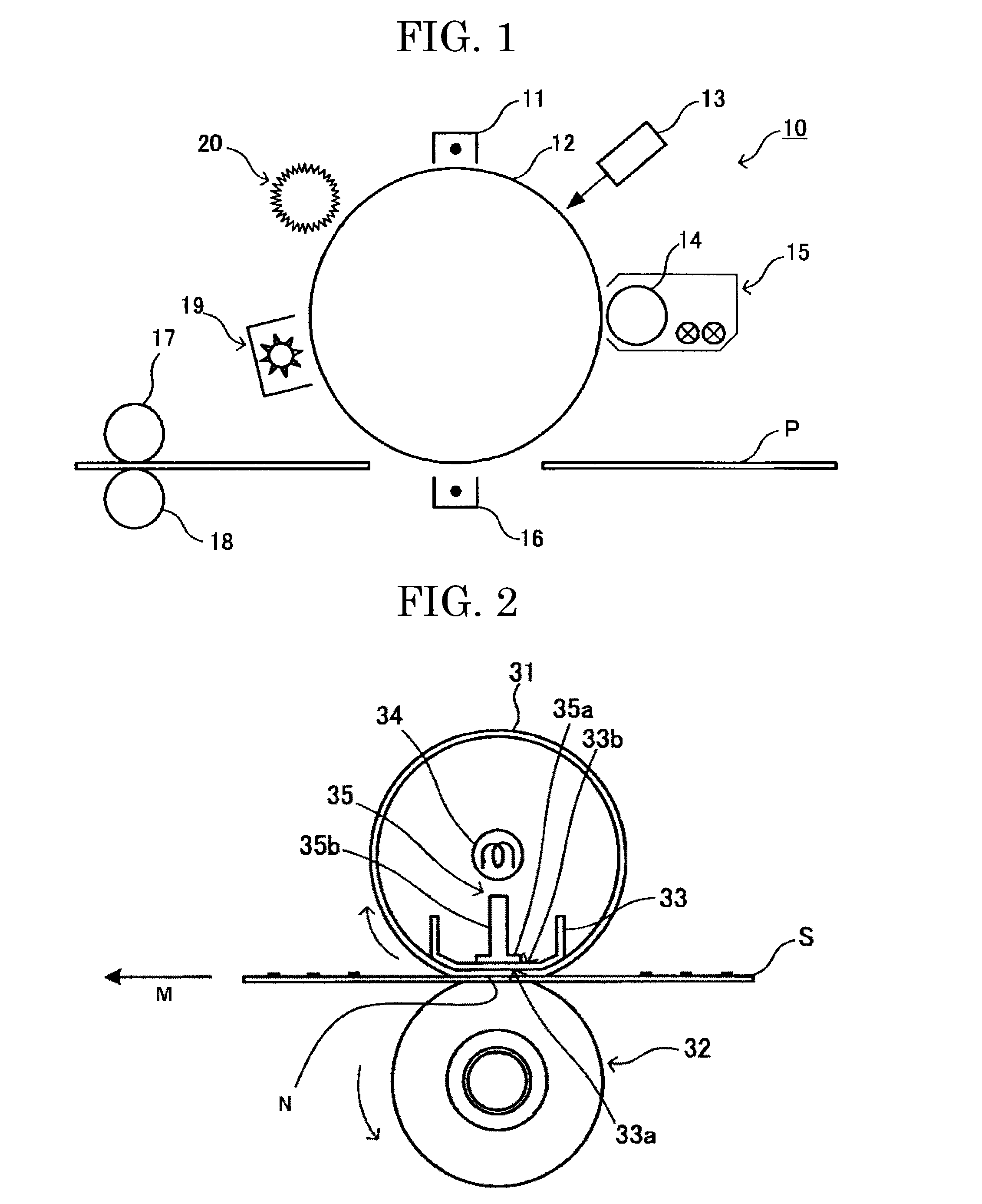
An image forming apparatus including: image bearing member; latent image forming unit; developing unit; transfer unit; fixing unit, wherein toner in the developing unit contains amorphous polymer, crystalline resin and releasing agent, when the toner is measured for G′ at 40° C. to 210° C. with rheometer at 1 Hz and 1 deg, G′(100) is ≦20,000 and G′(150) is ≧500 Pa, and straight line drawn by connecting points of the G′(100) and G′(110) on curve of the G′ has gradient of ≦0.035, the gradient being “a” expressed by: a=|log10G′(100)−log10G′(110)| / 10, and the fixing unit includes: heating member containing flexible endless belt; heat source fixed within the flexible endless belt; and press member in contact with the belt to form nip portion, and the fixing unit is configured to heat / press the medium passing through the nip portion to fix the image on the medium.

Description

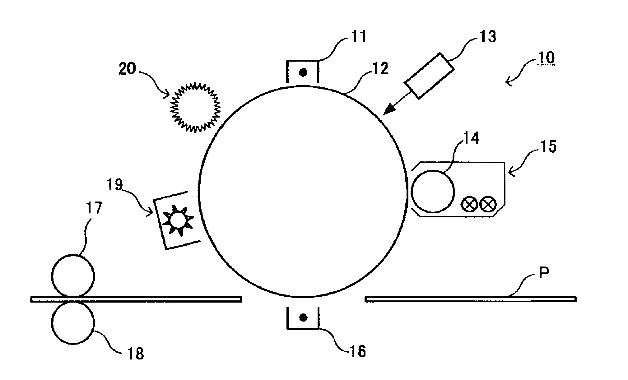
BACKGROUND OF THE INVENTION[0001]1. Field of the Invention[0002]The present invention relates to an image forming apparatus including: a fixing unit configured to form a nip portion between a flexible endless belt and a press member and perform fixing on a recording medium passing through the nip portion.[0003]2. Description of the Related Art[0004]An electrophotographic image forming apparatus forms a latent electrostatic image on the surface of a photoconductor drum serving as an image bearing member and develops the latent electrostatic image on the photoconductor drum with a developer such as an electrostatic image developing toner to form a visible toner image. The electrophotographic image forming apparatus is configured such that the toner image is transferred onto recording paper with a transfer device, and heat and pressure are applied with a fixing device to the recording paper onto which the toner image has been transferred, whereby the toner image on the recording paper ...

Claims


Application Information

Patent Timeline
Patent Type & Authority Patents(United States)
IPC IPC(8): G03G9/08G03G15/20G03G9/087
CPCG03G9/0821G03G15/2053G03G9/08797G03G2215/2035
Inventor KUSAHARA, TERUKISATOH, TOMOYUKIOGAWA, SATOSHIHIROHARA, KIWAKO
Owner RICOH KK
Learn More