
Image forming apparatus

a technology of forming apparatus and forming tube, which is applied in the direction of printing, instruments, printing, etc., can solve the problems of difficult shortening the conveying path by shortening recording material becomes liable to be caught by the sheet delivery guide, and the friction of the recording material passing is great, so as to shorten the output time of the first sheet

Active Publication Date: 2005-06-21
CANON KK
View PDF6 Cites 1 Cited by
  • Summary
  • Abstract
  • Description
  • Claims
  • Application Information

AI Technical Summary

Benefits of technology

[0023]Accordingly, it is the object of the present invention to solve the above-noted problem and to provide an image forming apparatus which can shorten the output time of the first sheet (first print-out time) and can be downsized.

Problems solved by technology

However, when the sheet delivery guide is constructed with a small radius of curvature, there is the evil that the frictional sound caused by the pass of the recording material becomes great or the recording material becomes liable to be caught by the sheet delivery guide.
Therefore, the sheet delivery guide after the image on the recording material has been fixed by the fixing means must be constructed with a gentle radius, and it has been difficult to shorten the conveying path by shortening the sheet delivery guide.
This has led to the problem that the recording material having had the image thereon fixed requires a long time until it enters a pair of sheet discharge rollers, and the first print-out time becomes long.

Method used


Image

  • Image forming apparatus
  • Image forming apparatus
  • Image forming apparatus

Examples


Embodiment Construction

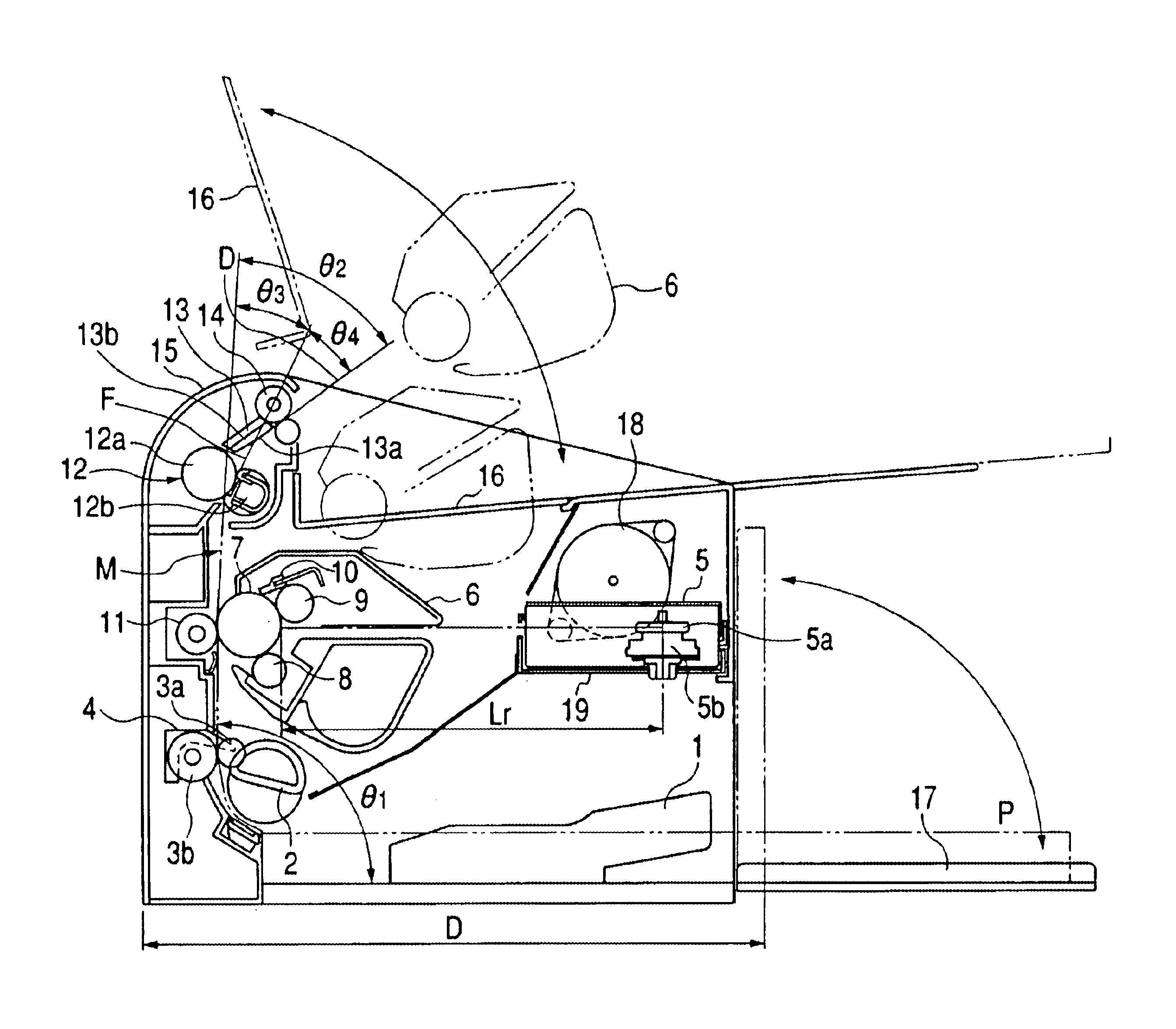
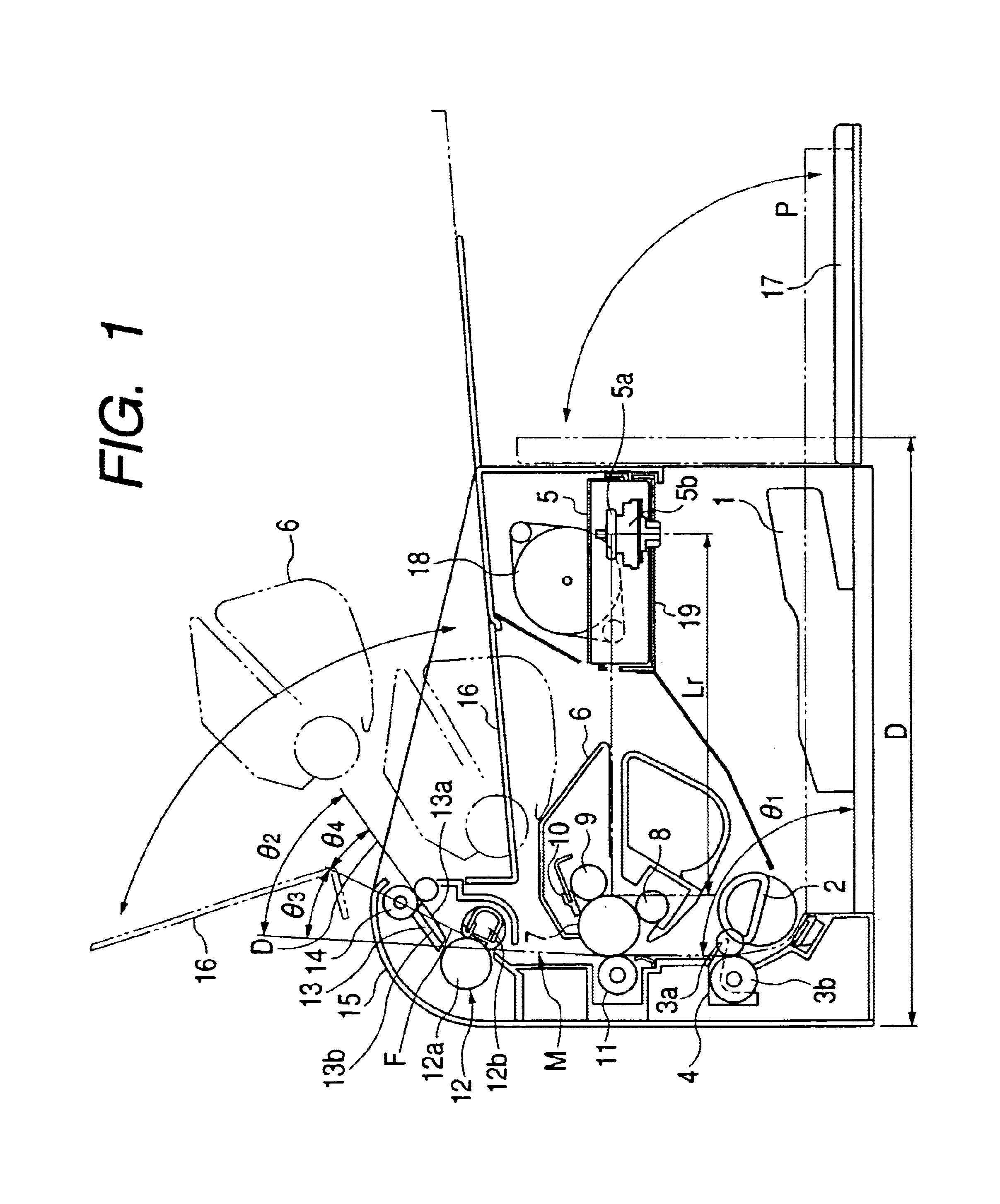
[0039]An embodiment of the present invention will hereinafter be described with reference to the drawings. Throughout the drawings of the following embodiment, like or corresponding portions are given like reference characters. FIG. 1 shows a laser beam printer which is an example of an image forming apparatus according to this embodiment.

[0040]In the laser beam printer according to this embodiment, there is adopted an electrophotographic process in which a laser beam is applied to a photosensitive member as an image bearing member and this laser beam is scanned to thereby effect recording.

[0041]That is, as shown in FIG. 1, in the laser beam printer according to this embodiment, there are provided a sheet supply portion 1 as a sheet placing portion, a sheet feeding roller 2 as sheet feeding means, conveying rollers 3a, 3b, a register sensor 4, a laser scanner 5 as optical means, and a process cartridge 6 as image forming means.

[0042]In the laser beam printer shown in FIG. 1, a plura...


PUM


Abstract

A sheet supply portion is disposed in the lowermost portion of a printer so as to be substantially horizontal. A main conveying path for guiding a sheet from a transferring roller to a fixing device is disposed in a substantially vertical direction so as to be along the back of the printer. The guide surface of a sheet delivery guide constituting a conveying path leading from the fixing device to a pair of sheet delivery rollers is a flat surface.

Description

BACKGROUND OF THE INVENTION[0001]1. Field of the Invention[0002]The invention relates to an image forming apparatus, and particularly is suitable for application to an image forming apparatus such as an electrophotographic copying machine, a printer, a word processor or a facsimile apparatus for forming an image on a recording medium.[0003]2. Description of Related Art[0004]The construction of a laser beam printer as an example of an image forming apparatus adopting an electrophotographic process or other recording process according to the conventional art is shown in FIGS. 4 and 5 of the accompanying drawings.[0005]In the laser beam printer according to the conventional art, there are a case where the conveying path of a recording material leading from sheet feeding means to fixing means via transferring means is set substantially horizontally as shown in FIG. 4, and a case where it is set obliquely as shown in FIG. 5.[0006]That is, in the laser beam printer shown in FIG. 4, a shee...

Claims


Application Information

Patent Timeline
Patent Type & Authority Patents(United States)
IPC IPC(8): G03B27/52G03B27/00B41J13/10
CPCB41J13/10
Inventor NODA, SHINYAKAWADE, TAKAAKIMUROOKA, KENNIIMURA, TAKESHIHAMADA, TATSUOTABA, YASUZUMIMIYAZAKI, HIDEKI
Owner CANON KK
Learn More